20
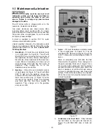
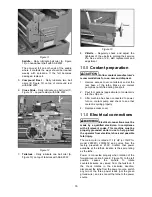
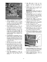
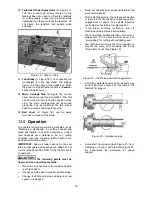
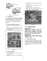
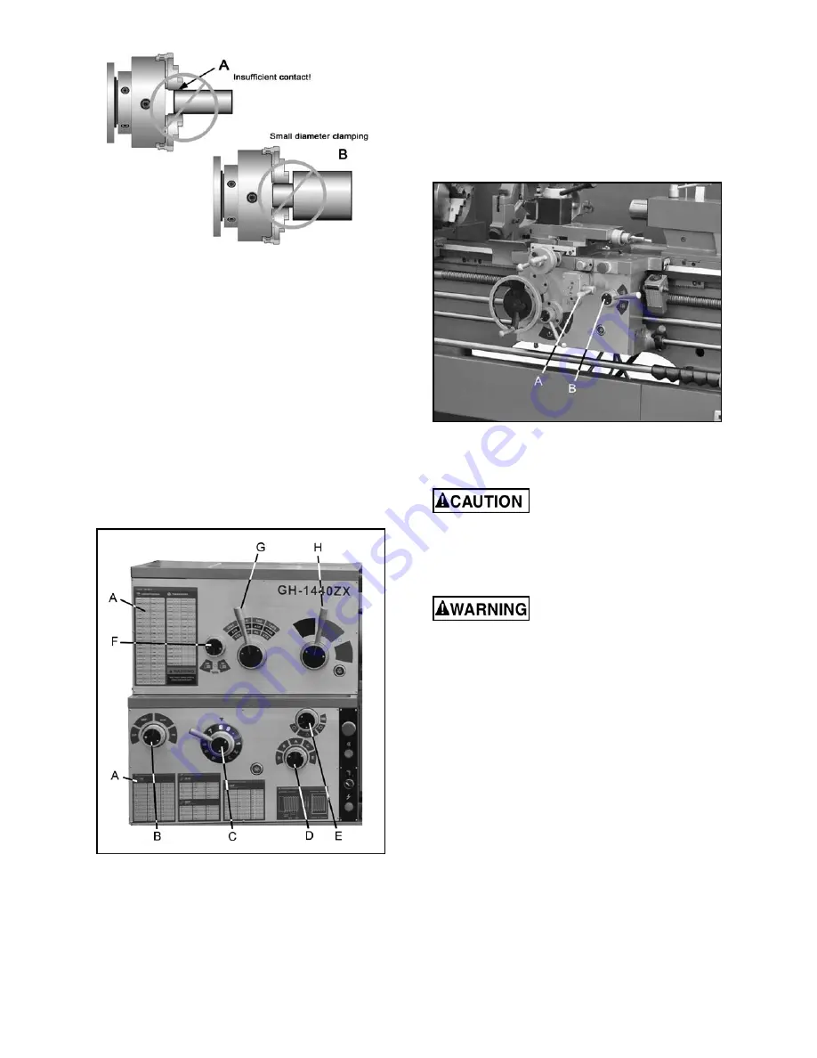
Figure 21 – Improper setups
13.1
Tool setup
The cutting angle is correct when the cutting edge
is in line with the center axis of workpiece. Use the
point of the tailstock center as a gauge and shims
under the tool to obtain correct center height.
Use a minimum of two clamping screws to secure
each tool.
13.2
Feed and thread selection
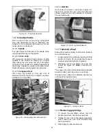
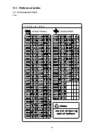
1. Reference the feed and thread chart (A, Figure
22).
2. Move levers and knobs (B/C/D/E, Figure 22) to
the appropriate position according to the feed
and thread chart.
Figure 22
13.3
Thread cutting
1. Set forward/reverse lever (F, Figure 22) to
desired direction.
2. Set selector levers (G/H, Figure 22) to desired
R.P.M.
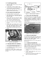
3. Select desired thread using levers (B/C/D/E,
Figure 22).
4. Set selector lever (A, Figure 23) to correct
position (neutral).
5. Engage the half nut lever (B, Figure 23).
6. Make a test cut with scrap material and check
results before cutting regular material.
Figure 23
14.0
Adjustments
Adjustments to the lathe,
especially those involving alignments of
bearings, spindle, leadscrew, clutch, etc.,
should only be performed by qualified
personnel, as improper alignments can damage
the machine and/or create a safety hazard.
Turn off main switch and press
emergency stop button before making
adjustments to lathe.
14.1
Chuck jaw reversal
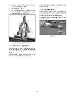
The three jaws on the scroll chuck are reversible,
to hold stock with larger diameters. See Figure 24.
Loosen two screws with the provided hex key,
remove jaw, and rotate it 180-degrees. Re-install
jaw, and tighten each screw in increments until fully
tightened.
Summary of Contents for GH-1440ZX
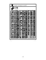
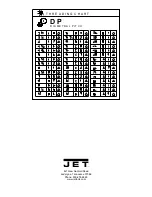
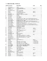
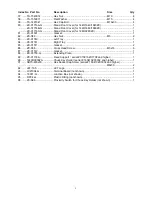
Page 26: ...26 T H R E A D I N G C H A R T I N I N C H ...
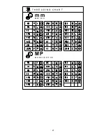
Page 27: ...27 m m M E T R I C T H R E A D I N G C H A R T M P M O D U L E P I T C H ...
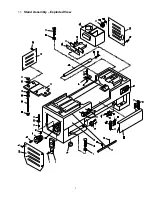
Page 31: ...3 1 1 Stand Assembly Exploded View ...
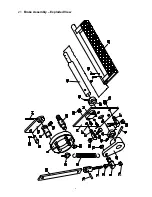
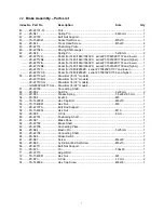
Page 34: ...6 2 1 Brake Assembly Exploded View ...
Page 36: ...8 3 1 Bed Assembly Exploded View ...
Page 39: ...11 4 1 Headstock Assembly I Exploded View ...
Page 43: ...15 5 1 Headstock Assembly II Exploded View ...
Page 46: ...18 6 1 Headstock Assembly III Exploded View ...
Page 48: ...20 7 1 Headstock Assembly IV Exploded View ...
Page 50: ...22 8 1 Change Gear Box Assembly I Exploded View ...
Page 52: ...24 9 1 Change Gear Box Assembly II Exploded View ...
Page 54: ...26 10 1 Quick Change Gear Box I Exploded View ...
Page 57: ...29 11 1 Quick Change Gear Box II Exploded View ...
Page 59: ...31 12 1 Quick Change Gear Box III Exploded View ...
Page 61: ...33 13 1 Apron Assembly I Exploded View ...
Page 64: ...36 14 1 Apron Assembly II Exploded View ...
Page 67: ...39 15 1 Apron Assembly III Exploded View ...
Page 69: ...41 16 1 Carriage Assembly Exploded View ...
Page 73: ...45 18 1 Carriage Stop Assembly Exploded View ...
Page 75: ...47 19 1 Quick Change Tool Post Exploded View ...
Page 77: ...49 20 1 Tailstock Assembly I Exploded View ...
Page 79: ...51 21 1 Tailstock Assembly II Exploded View ...
Page 81: ...53 22 1 Steady Rest Assembly Exploded View ...
Page 83: ...55 23 1 Follow Rest Assembly Exploded View ...
Page 85: ...57 24 1 Coolant Work Light Assembly Exploded View ...
Page 89: ...61 26 2 Electrical Cabinet Breakdown 6 7 8 12 11 10 17 22 21 23 13 9 9a 20 18 3a 1 2 4 19 3 ...
Page 90: ...62 27 0 Wiring Diagram ...
Page 94: ...66 427 New Sanford Road LaVergne Tennessee 37086 Phone 800 274 6848 www jettools com ...

