23
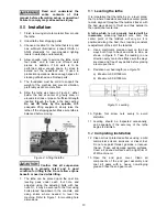
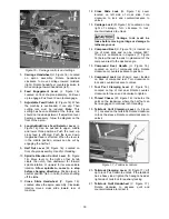
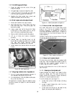
4. Pivot the collar on its hinge and position
steady rest around workpiece.
5. Firmly tighten hex nut (A).
6. Set the fingers snugly to work piece and
secure by tightening locking knobs.
Fingers
should be snug but not overly tight.
Figure 31 – Steady rest adjustment
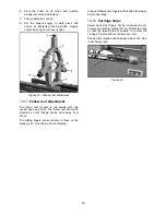
14.11
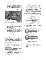
Follow rest adjustment
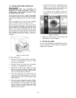
The follow rest mounts to the saddle with two
socket head cap bolts. The follow rest should be
mounted so that locking knobs point away from
chuck.
The sliding fingers are set similar to those on the
steady rest – free of play, but not binding.
Always lubricate the fingers sufficiently with grease
before operating.
14.12
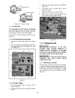
Carriage stops
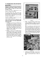
Adjust each stop (Figure 32) by loosening two set
screws, and sliding it along the rod. Rotate the stop
so that the raised area is upward to contact the
carriage. Tighten both set screws securely.
Position the raised area downward when the stop
is not being used.
Figure 32
Summary of Contents for GH-1440ZX
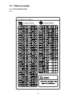
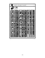
Page 26: ...26 T H R E A D I N G C H A R T I N I N C H ...
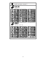
Page 27: ...27 m m M E T R I C T H R E A D I N G C H A R T M P M O D U L E P I T C H ...
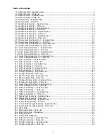
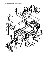
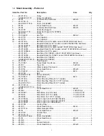
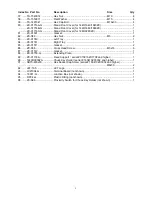
Page 31: ...3 1 1 Stand Assembly Exploded View ...
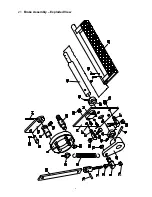
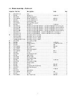
Page 34: ...6 2 1 Brake Assembly Exploded View ...
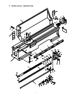
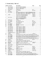
Page 36: ...8 3 1 Bed Assembly Exploded View ...
Page 39: ...11 4 1 Headstock Assembly I Exploded View ...
Page 43: ...15 5 1 Headstock Assembly II Exploded View ...
Page 46: ...18 6 1 Headstock Assembly III Exploded View ...
Page 48: ...20 7 1 Headstock Assembly IV Exploded View ...
Page 50: ...22 8 1 Change Gear Box Assembly I Exploded View ...
Page 52: ...24 9 1 Change Gear Box Assembly II Exploded View ...
Page 54: ...26 10 1 Quick Change Gear Box I Exploded View ...
Page 57: ...29 11 1 Quick Change Gear Box II Exploded View ...
Page 59: ...31 12 1 Quick Change Gear Box III Exploded View ...
Page 61: ...33 13 1 Apron Assembly I Exploded View ...
Page 64: ...36 14 1 Apron Assembly II Exploded View ...
Page 67: ...39 15 1 Apron Assembly III Exploded View ...
Page 69: ...41 16 1 Carriage Assembly Exploded View ...
Page 73: ...45 18 1 Carriage Stop Assembly Exploded View ...
Page 75: ...47 19 1 Quick Change Tool Post Exploded View ...
Page 77: ...49 20 1 Tailstock Assembly I Exploded View ...
Page 79: ...51 21 1 Tailstock Assembly II Exploded View ...
Page 81: ...53 22 1 Steady Rest Assembly Exploded View ...
Page 83: ...55 23 1 Follow Rest Assembly Exploded View ...
Page 85: ...57 24 1 Coolant Work Light Assembly Exploded View ...
Page 89: ...61 26 2 Electrical Cabinet Breakdown 6 7 8 12 11 10 17 22 21 23 13 9 9a 20 18 3a 1 2 4 19 3 ...
Page 90: ...62 27 0 Wiring Diagram ...
Page 94: ...66 427 New Sanford Road LaVergne Tennessee 37086 Phone 800 274 6848 www jettools com ...

