background image


51

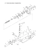
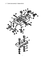
21.1

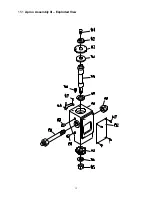
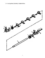
  Tailstock Assembly II – Exploded View 


Summary of Contents for GH-1440ZX

Page 1: ...1440ZX GH 1640ZX 1660ZX GH 1860ZX 1880ZX GH 2280ZX Model GH 1440ZX shown For ZX Series Lathes Parts List Electrical Diagrams see document M 321910 1 JET 427 New Sanford Road LaVergne TN 37086 Part No M 321910 Ph 800 274 6848 Revision J2 08 2018 www jettools com Copyright 2017 JET ...

Page 2: ...me caution and replace the guards immediately 15 Check damaged parts Before further use of the machine a guard or other part that is damaged should be carefully checked to determine that it will operate properly and perform its intended function Check for alignment of moving parts binding of moving parts breakage of parts mounting and any other conditions that may affect its operation A guard or o...

Page 3: ... lead from lead based paint crystalline silica from bricks cement and other masonry products arsenic and chromium from chemically treated lumber Your risk of exposure varies depending on how often you do this type of work To reduce your exposure to these chemicals work in a well ventilated area and work with approved safety equipment such as dust masks that are specifically designed to filter out ...

Page 4: ...our area call 1 800 274 6846 or use the Service Center Locator on the JET website More Information JET is constantly adding new products For complete up to date product information check with your local distributor or visit the JET website How State Law Applies This warranty gives you specific legal rights subject to applicable state law Limitations on This Warranty JET LIMITS ALL IMPLIED WARRANTI...

Page 5: ...period 14 9 0 Maintenance Lubrication 15 10 0 Coolant preparation 16 11 0 Electrical connections 16 11 1 Conversion to 460 volt operation 17 12 0 Controls 17 13 0 Operation 19 13 1 Tool setup 20 13 2 Feed and thread selection 20 13 3 Thread cutting 20 14 0 Adjustments 20 14 1 Chuck jaw reversal 20 14 2 Gib adjustments 21 14 3 Tailstock off set 21 14 4 Removing gap bridge 21 14 5 Installing gap bri...

Page 6: ...2 to 1800 Gearbox Number of Longitudinal and Cross Feeds 46 31 Range of Longitudinal Feeds in rev 0 0015 to 0 0900 Range of Cross Feeds in rev 0 0010 to 0 0360 Number of Inch Threads 61 Range of Inch Threads in 1 5 8 to 72 Number of Metric Threads 24 Range of Metric Threads mm 0 50 to 20 0 Number of Diametral Threads 45 Range of Diametral Threads 3 1 4 96DP Number of Module Threads 20 Range of Mod...

Page 7: ...0360 Number of Inch Threads 61 61 Range of Inch Threads in 1 5 8 to 72 1 5 8 to 72 Number of Metric Threads 24 24 Range of Metric Threads mm 0 50 to 20 0 0 50 to 20 0 Number of Diametral Threads 45 45 Range of Diametral Threads 3 1 4 96DP 3 1 4 96DP Number of Module Threads 20 20 Range of Module Threads 0 25 10MP 0 25 10MP Compound and Carriage Maximum Compound Slide Travel in 5 1 8 5 1 8 Maximum ...

Page 8: ... Number of Inch Threads 61 61 Range of Inch Threads in 1 5 8 to 72 1 5 8 to 72 Number of Metric Threads 24 24 Range of Metric Threads mm 0 50 to 20 0 0 50 to 20 0 Number of Diametral Threads 45 45 Range of Diametral Threads 3 1 4 96DP 3 1 4 96DP Number of Module Threads 20 20 Range of Module Threads 0 25 10MP 0 25 10MP Compound and Carriage Maximum Compound Slide Travel in 5 1 8 5 1 8 Maximum Cros...

Page 9: ...eeds in rev 0 0010 to 0 0360 Number of Inch Threads 61 Range of Inch Threads in 1 5 8 to 72 Number of Metric Threads 24 Range of Metric Threads mm 0 50to 20 0 Number of Diametral Threads 45 Range of Diametral Threads 3 1 4 96DP Number of Module Threads 20 Range of Module Threads 0 25 10MP Compound and Carriage Maximum Compound Slide Travel in 5 1 8 Maximum Cross Slide Travel in 12 Carriage Travel ...

Page 10: ...s made from high quality cast iron and is mounted to the left side of the machine bed Carriage The carriage assembly is composed of the Apron the Saddle the Cross Slide the Compound Rest and the four way Tool Post Apron G Quick travel of the Apron for positioning is accomplished by means of a bed mounted rack and pinion operated manually by the handwheel on the front of the apron or automatically ...

Page 11: ...nto position at any point along the rod to limit travel of the carriage Thread chaser R Simplifies the process of setting leadscrew carriage positions in relation to the workpiece by indicating the point on the leadscrew where the half nut can be reengaged to continue threading Steady rest S The steady rest serves as a support for shafts on the free tailstock end The steady rest is mounted on the ...

Page 12: ...est mounted on Lathe 1 10 Three Jaw Chuck mounted on Lathe 1 Face Plate 12 Face Plate for 14 16 lathes 16 Face Plate for 18 22 lathes 1 Tool Box containing 1 Open End Wrench Set 1 Hex Wrench Set 1 Morse Reduction Sleeve 1 Center 6 Leveling Bolts with Hex Nuts 2 Hex Screws with Washers 6 Leveling Pads 1 Flat Blade Screwdriver 1 Cross Point Screwdriver 1 Chuck Wrench 1 Cam Wrench 1 Adjustable Wrench...

Page 13: ...justed using the adjusting bolts with hex nuts Or it may be secured to the floor using bolts placed head down in the concrete and using shims where needed to level the machine Refer to Figure 1 for mounting hole dimensions 8 1 Leveling the lathe It is imperative that the lathe be on a level plane that is where headstock and tailstock center points remain aligned throughout the tailstock travel wit...

Page 14: ...lly remove the chuck from the spindle and place on an adequate work surface 3 Inspect the camlock studs Make sure they have not become cracked or broken during transit Clean all parts thoroughly with solvent Also clean the spindle and camlocks 4 Cover all chuck jaws and scroll inside the chuck with 2 lithium tube grease Cover the spindle camlocks and chuck body with a light film of 20W oil 5 Lift ...

Page 15: ...tal shavings Refill after the first month of operation Then change the oil in the headstock every two months 2 Gearbox Oil must be up to indicator mark in oil sight glass B Figure 9 Top off with SAE 20W To add oil to the gearbox remove two screws on the top cover and remove cover To drain remove drain plug C Figure 9 on the left side of the gearbox Drain oil completely and refill after the first t...

Page 16: ...ot shifted during transport 2 Pour four gallons approximate of coolant mix into the chip pan 3 After machine has been connected to power turn on coolant pump and check to see that coolant is cycling properly 4 Replace access cover 11 0 Electrical connections Electrical connections must be made by a qualified electrician in compliance with all relevant codes This machine must be properly grounded w...

Page 17: ...properly grounded Figure 14 Power input 12 0 Controls Figure 15 Headstock controls 1 Control Panel located on front of headstock Coolant On Off Switch A Figure 15 turns coolant pump on and off Power Indicator Light D Figure 15 is lit whenever lathe is receiving power Emergency Stop Switch C Figure 15 stops all machine functions Caution Lathe will still have power Twist clockwise to re set Jog Swit...

Page 18: ...ted above the apron assembly Clockwise rotation moves cross slide toward rear of machine 12 Cross Slide Lock Q Figure 16 Lever located on left side of cross slide Turn clockwise to lock and counterclockwise to unlock 13 Carriage Lock R Figure 16 Located on top right of carriage Turn clockwise to lock counterclockwise to unlock Carriage lock must be loose before moving carriage or damage to lathe m...

Page 19: ...ce quality IMPORTANT Allow a break in period for the new lathe so that gears and bearings can adapt do not run the lathe above 560 RPM for the first six hours of operation The following points must be observed when operating the lathe Never turn any handles or levers when spindle is at high speed Change spindle speed only after spindle stops Change feed rate only when spindle is at low speed or is...

Page 20: ...red thread using levers B C D E Figure 22 4 Set selector lever A Figure 23 to correct position neutral 5 Engage the half nut lever B Figure 23 6 Make a test cut with scrap material and check results before cutting regular material Figure 23 14 0 Adjustments Adjustments to the lathe especially those involving alignments of bearings spindle leadscrew clutch etc should only be performed by qualified ...

Page 21: ...de and rest 14 2 4 Half Nut Gib screws are located on right side of apron C Figure 26 Loosen the jam nuts and rotate the screws clockwise until any backlash is corrected Then re tighten nuts Figure 26 Half nut gib adjustment 14 3 Tailstock off set Follow the procedure below to off set the tailstock to cut shallow tapers 1 Loosen tailstock in position by lowering locking handle B Figure 27 and loos...

Page 22: ...de and traverse the center line of the bar If adjustment is needed align the tailstock using the off set screws D Figure 27 until the tailstock is aligned Figure 29 Tailstock Headstock alignment 14 8 Cross slide nut adjustment The cross slide moves via a lead screw which drives a nut This can be adjusted if backlash develops Backlash is identified by turning the cross slide handwheel left and righ...

Page 23: ...ead cap bolts The follow rest should be mounted so that locking knobs point away from chuck The sliding fingers are set similar to those on the steady rest free of play but not binding Always lubricate the fingers sufficiently with grease before operating 14 12 Carriage stops Adjust each stop Figure 32 by loosening two set screws and sliding it along the rod Rotate the stop so that the raised area...

Page 24: ...aces light coat of oil SAE 20W machine oil frequently 9 0 Headstock Drain and fill SAE 20W machine oil after 30 days every 2 months 9 0 Gearbox Drain and fill SAE 20W machine oil after first 3 months every 6 months 9 0 Apron and Saddle Drain and fill SAE 20W machine oil after first 3 months then annually 9 0 Leadscrew Feed Rod Spindle Direction Control Axle Fill at ball oilers SAE 20W machine oil ...

Page 25: ...25 16 0 Reference tables 16 1 Inch Lead And Feed Table 2 F E E D I N R E V LONGITUDINAL TRANSVERSE ...

Page 26: ...26 T H R E A D I N G C H A R T I N I N C H ...

Page 27: ...27 m m M E T R I C T H R E A D I N G C H A R T M P M O D U L E P I T C H ...

Page 28: ...28 D P D I A M E T R A L P I T C H T H R E A D I N G C H A R T 427 New Sanford Road LaVergne Tennessee 37086 Phone 800 274 6848 www jettools com ...

Page 29: ...40ZX GH 1640ZX 1660ZX GH 1860ZX 1880ZX GH 2280ZX For ZX Series Lathes Operating Instructions see document M 321910 JET 427 New Sanford Road LaVergne Tennessee 37086 Ph 800 274 6848 Model GH 1440ZX shown www jettools com Part No M 321910 1 Revision J 10 2017 Copyright 2017 JET ...

Page 30: ...ron Assembly I Parts List 34 14 1 Apron Assembly II Exploded View 36 14 2 Apron Assembly II Parts List 37 15 1 Apron Assembly III Exploded View 39 15 2 Apron Assembly III Parts List 40 16 1 Carriage Assembly Exploded View 41 16 2 Carriage Assembly Parts List 42 17 1 Micro Carriage Stop Exploded View 44 17 2 Micro Carriage Stop Parts List 44 18 1 Carriage Stop Assembly Exploded View 45 18 2 Carriag...

Page 31: ...3 1 1 Stand Assembly Exploded View ...

Page 32: ...X 01102 G Bed Stand for 2280ZX 1 11 ZX 01703 Fixed Support 1 12 TS 150341 Socket Head Cap Screw M6x14 4 13 ZX S13 Taper Pin 5x20 mm 2 14 ZX 01705 Water Leaking Chip Guard 1 15 ZX S15A Cross Head Screw M5x20 4 16 TS 1540121 Hex Nut M20 9 17 ZX 01702 Bolt 3 ML 2080 01704 Bolt for 2280ZX 3 18 TS 1550111 Flat Washer M20 6 19 ZX 01122A Motor Mounting Plate for 14 models 1 ZX 01122B Motor Mounting Plate...

Page 33: ...1740 Left Tray 1 84 ZX 01741 Right Tray 1 85 ZX 01511 Gasket 2 86 ZX S86 Cross Head Screw M5x16 6 87 ZX 01512 Gasket 1 88 ZX 05753 G Extending Plate 1 89 ZX 01703A Fixed Support serial 070916ZX1738 and higher 1 90 1440R09302A Chuck Key Holder serial 160410ZX3032 and higher 1 91 GB70 M8x50 Hex Socket Cap Screw serial 160410ZX3032 and higher M8x50 2 92 JET 165 JET Logo 1 93 JX21004 G Terminal Board ...

Page 34: ...6 2 1 Brake Assembly Exploded View ...

Page 35: ...2280ZX serial 070916ZX1738 and higher 1 50 ZX 22710A G Draw Bar for 14 models 1 ZX 22710B G Draw Bar for 16 models 1 ZX 22710C G Draw Bar for 18 models 1 GH2280ZX 22710 G Draw Bar for 22 model 1 51 ZX 22706 Connecting Shaft 1 52 ZX S52 Split Pin 2x20 mm 2 53 ZX S53 Tensile Spring 3 5x26x190 mm 1 54 ZX S54 Eyebolt M8 1 55 TS 1490091 Hex Cap Bolt M8x50 1 56 TS 1540061 Hex Nut M8 1 57 ZX 22707A Butt ...

Page 36: ...8 3 1 Bed Assembly Exploded View ...

Page 37: ...for 1880ZX 1 GH2280ZX 12701 G Splash Guard for 2280ZX 1 18 ZX B18 Shear Pin 5x35 mm 2 19 ZX 01708A Lead Screw for 40 models serial 010611ZX349 and lower 1 ZX 01708AN New Lead Screw for 40 models serial 010618ZX350 and higher 1 ZX 01708B Lead Screw for 60 models serial 010611ZX349 and lower 1 ZX 01708BN New Lead Screw for 60 models serial 010618ZX350 and higher 1 ZX 01708C Lead Screw for 80 models ...

Page 38: ...Long Lever Sleeve 1 46 ZX B46 Hex Nut M8 2 47 ZX B47 Set Screw M8x28 2 48 ZX 06001C 5 Direction Change Ring 1 49 ZX B49 Pin 8n6x20 1 50 ZX B50 Taper Pin 3x20 mm 1 51 TS 1505081 Socket Cap Screw M10x50 2 52 ZX 05741 Threaded Tube 2 53 TS 1540081 Hex Nut M12 2 54 ZX B54 Drum Switch 1 55 ZX S27 Cross Head Screw M5x8 5 56 ZX 01718 Rocker 1 57 ZX B57 Pin 3x16 mm 1 58 ZX 01716 G Bracket 1 59 ZX 01715C G...

Page 39: ...11 4 1 Headstock Assembly I Exploded View ...

Page 40: ...5x2 4 mm 1 20 ZX H20 Pin 5x30 mm 1 21 ZX 02734 Shaft 1 22 ZX H10 Woodruff Key 4x16 mm 1 23 ZX H5 Steel Ball 8 1 24 ZX H4 Spring YI 1x8x25 1 25 ZX H3 Flat End Set Screw M10x12 1 26 ZX 02733 G Left Positioning Disc 1 27 ZX H6 Countersunk Head Screw M5x12 2 28 ZX 02113 G Left Lever Support 1 29 ZX 02741 Handle 2 30 ZX 02732 Cover 2 31 ZX H6 Countersunk Head Screw M5x12 1 32 ZX H6 Countersunk Head Scr...

Page 41: ...er 1 ZX 02301BJ Label for 1460ZX serial 160401ZX3031 and lower 1 ZX 02301 298 Label for 1460ZX serial 160410ZX3032 and higher 1 ZX 02301C Label for 1640ZX serial 110915ZX2363 and lower 1 ZX 02301CJ Label for 1640ZX serial 160401ZX3031 and lower 1 ZX 02301 299 Label for 1640ZX serial 160410ZX3032 and higher 1 ZX 02301D Label for 1660ZX serial 110915ZX2363 and lower 1 ZX 02301DJ Label for 1660ZX ser...

Page 42: ...per Gasket 1 93 TS 1531012 Slotted Pan Head Screw serial 160401ZX3031 and lower M3x6 7 GB2672 M3x6 Screw serial 160410ZX3032 and higher M3x6 11 94 ZX H94N Pin 4n6x15 2 95 ZX 02740 Front Cover 1 96 GB97 2 6 Washer 6 mm 2 97 GB818 M6x8 Cross Head Screw M6x8 2 ...

Page 43: ...15 5 1 Headstock Assembly II Exploded View ...

Page 44: ...rew M6x20 1 116 ZX H59 Pin 3n6x10 1 117 ZX H117 Ring Seal 60x3 1 mm 1 118 ZX 02104 G Blocking Flange 1 119 TS 1503041 Socket Cap Screw M6x15 3 120 TS 1503041 Socket Cap Screw M6x15 3 121 ZX 02103 Blocking Flange serial 110710ZX2337 and lower 1 ZX 19101 G Blocking Flange serial 110825ZX2338 and higher 1 122 ZX H117 Ring Seal 60x3 1 mm 1 123 BB 6305 P5 Ball Bearing 25x62x17 1 124 ZX H124 Sleeve 62x6...

Page 45: ...Key 5x5x1 1 202 ZX H198 C Clip 28 mm 1 203 ZX 02722C Sleeve 1 204 ZX 02301 Oil Bushing serial 101029ZX2256 and lower 1 CDL50002302 Oil Bushing serial 101214ZX2257 and higher 1 205 ZX 08106A G Bracket for Shaft V Vb for 14 16 models 1 ZX 08106B G Bracket for Shaft V Vb for 18 models 1 GH2280ZX 08106 G Bracket for Shaft V Vb Vc for 22 model 1 206 ZX H77 Taper Pin 8x40 mm 1 207 TS 1505031 Hex Socket ...

Page 46: ...18 6 1 Headstock Assembly III Exploded View ...

Page 47: ... lower 1 ZX H212A Drain Plug 14 models serial 010105ZX263 and higher 1 ZX H212A Drain Plug 16 models serial 010319ZX294 and higher except for serial 010319ZX298 and 299 1 ZX H212A Drain Plug 18 models serial 010514ZX323 and higher 1 ZX H212A Drain Plug 22 model Z3 8 1 213 ZX 02101A Headstock Casting 14 models serial 001204ZX258 and lower 1 ZX 02101AN Headstock Casting 14 models serial 010105ZX263 ...

Page 48: ...20 7 1 Headstock Assembly IV Exploded View ...

Page 49: ...ront Side Plate for 18 models 1 GH2280ZX 08113 G Front Side Plate for 22 model 1 217 TS 1504051 Socket Cap Screw M8x25 4 218 ZX H218 Taper Pin 6x25 mm 2 219 TS 1503051 Socket Cap Screw M6x20 8 220 TS 1514021 Socket Cap Screw M6x15 3 220a GB97 2 6 Washer 6 mm 3 222 ZX 08712 Upper Hinge 2 223 ZX H223 Pin 6n6x40 2 225 ZX 08711 Lower Hinge 2 226 GH 1440ZX 11304 6 Warning Plate serial 160410ZX3032 and ...

Page 50: ...22 8 1 Change Gear Box Assembly I Exploded View ...

Page 51: ...rank 1 15 ZX 08110 Bushing 1 16 ZX 08704 Rotating Shaft 1 17 ZX 08703 Connecting Rod 1 18 ZX 08304 Sliding Block 1 26 ZX C26 Cross Head Screw M4x12 3 28 TS 1504051 Socket Cap Screw M8x25 4 29 TS 1516051 Hex Socket Cap Screw M10x40 2 30 TS 1525021 Set Screw M10x12 1 31 ZX C31 Flat Head Set Screw M6x8 1 33 ZX C33 Taper Pin 4x45 mm 1 34 ZX C34 Taper Pin 6x30 mm 2 35 ZX C35 Taper Pin 6x50 mm 1 36 ZX C...

Page 52: ...24 9 1 Change Gear Box Assembly II Exploded View ...

Page 53: ... 32 ZX C32 Flat Head Set Screw M10x12 1 39 BB 6203ZZ P6 Ball Bearing 17x40x12 5 40 ZX C40 C Clip 25 mm 4 5 for 22 41 ZX C41 C Clip 40 mm 1 43 ZX C43 Oil Cup 8 mm 1 2 for 22 44 TNMP08108 Washer 1 2 for 22 45 TNMP08102 Splined Sleeve 1 46 TNMP08504 Gear 3m41T 1 47 TNMP08501A Gear for 14 16 22 models 3 5m36T 1 TNMP08501B Gear for 18 models 4m36T 1 48 ZX 05502C Oil Bushing 1 49 ZX 08707 Shaft Vb 1 50 ...

Page 54: ...26 10 1 Quick Change Gear Box I Exploded View ...

Page 55: ... Fork 1 29 ZX Q29 Ring Seal 32x3 1 mm 1 30 ZX Q30 Taper Pin serial 121220ZX2630 and lower 4x25 mm 2 GB877 4x30 Taper Pin serial 130102ZX2631 and higher 4x30 mm 2 31 ZX 05129 Cover 1 32 ZX Q32 Pin 5n6x15 1 33 ZX Q33 Cheese Head Screw M5x16 3 34 ZX 05122 Cam 1 35 ZX 05728 Rolling Sleeve 5 36 ZX 05729 Poking Key 3 37 ZX 05123 Crank 1 38 ZX Q38 Pin 8n6x32 5 39 ZX Q39 Pin 6n6x20 mm 5 40 ZX 05124 Crank ...

Page 56: ...10ZX3032 and higher M3x6 11 69 ZX Q69 Oil Sight Glass 20 mm 1 70 ZX 05727 Positioning Disc 1 71 ZX Q71 Countersunk Head Screw M4x12 9 72 ZX 05740 G Lever 1 73 ZX 05130A G Lever Support 1 74 ZX 05301 Sign Disc serial 160401ZX3031 and lower 2 C6136ZK 02304 1 Sign Disc serial 160410ZX3032 and higher 2 74a ZX 05301 Sign Disc serial 160401ZX3031 and lower 1 C6136 02306 Sign Disc serial 160410ZX3032 and...

Page 57: ...29 11 1 Quick Change Gear Box II Exploded View ...

Page 58: ...ear 3 25m22T 1 96 ZX 05714 Double Gear 3 25m24T 3 25m23T 1 97 BB 6205 Single Row Radial Ball Bearing 25x52x15 mm 2 98 ZX C40 C Clip 25 mm 3 99 ZX 05125 G Shaft End Cover 1 100 TS 1504041 Hex Socket Cap Screw M8x18 2 101 ZX 05704 Spacer 1 102 ZX 05705 Double Gear 2m52T 2m26T 1 103 ZX 05502C Oil Bushing 3 104 ZX 05105 Sleeve 2 105 ZX 05707 Double Gear 2m39T 2m26T 1 106 ZX Q106 Iron Wire 1x160 mm 3 1...

Page 59: ...31 12 1 Quick Change Gear Box III Exploded View ...

Page 60: ...BB 51105 Thrust Bearing 25x42x11 mm 2 122 ZX Q122 Spacer 25 mm 2 123 BB 6305 Ball Bearing 25x62x17 mm 1 124 ZX 05725 Shaft 1 125 ZX Q125 Key 8x7x50 mm 1 126 ZX 05724 Double Gear 2 25m35T 2 25m36T 1 127 ZX 05723 Gear 2 5m36T 1 128 ZX 05107 Sleeve 2 129 BB 6005 Ball Bearing 25x47x12 mm 1 130 TS 1525021 Set Screw M10x12 2 131 ZX 05103 Bearing Support 1 132 ZX 05701 Shaft 1 133 ZX Q133 Half Circle Key...

Page 61: ...33 13 1 Apron Assembly I Exploded View ...

Page 62: ...1 Set Screw M6x10 1 27 ZX 06733 Half Nut Control Plate 1 28 ZX A28 Taper Pin 6x55 mm 1 29 ZX 06732 Pin 2 30 ZX 06302 Half Nut serial 010611ZX349 and lower 1 ZX 06302N New Half Nut serial 010618ZX350 and higher 1 31 TS 1540072 Hex Nut M10 1 32 ZX A32 Cylindrical End Set Screw M10x60 1 33 ZX 06121 Gib 1 34 ZX 06731 Cylindrical End Set Screw 3 35 TS 1540061 Hex Nut M8 3 36 ZX A36 Set Screw M8x32 1 37...

Page 63: ... A130 Taper Pin 4x20 mm 1 131 TS 1524031 Set Screw M8x12 2 132 ZX A132 Screw M8x25 2 133 ZX A133 Cylindrical Tensile Spring LI 1 6x10x58 1 134 TL06503 Gasket 1 135 TL06114 G Back Cover 1 136 TS 1514011 Hex Socket Cap Screw M6x12 5 137 ZX A137 Set Screw M8x30 2 138 ZX A138 Iron Wire 1x50 mm 2 139 ZX A139 Oil Conducting Cord 3x100 mm 2 140 ZX A140 Screw M10x40 1 158 TS 1540041 Hex Nut M6 1 159 TL061...

Page 64: ...36 14 1 Apron Assembly II Exploded View ...

Page 65: ...1 63 TS1514011 Hex Socket Cap Screw M6x12 3 64 TL06733 T Shaped Flat Key 1 65 TL06115 Flange Sleeve 1 66 TS1514011 Hex Socket Cap Screw M6x12 3 67 ZXA67 Flat End Set Screw M6x30 1 68 TS1540041 Hex Nut M6 1 76 TL06109 G Flange 1 77 TS1514011 Hex Socket Cap Screw M6x12 3 78 TL06303 Sign Plate serial 160401ZX3031 and lower 1 TL06303 1 Sign Plate serial 160410ZX3032 and higher 1 79 TL06714 Adjusting S...

Page 66: ...115 Oil Seal 50x3 1 mm 1 116 TL06119 Lever Flange 1 117 TS1514011 Hex Socket Cap Screw M6x12 3 118 TL06118 Lever Support serial 120520ZX2472 and lower 1 TL06118 G Lever Support 1 119 TL06307 Sign Plate serial 160401ZX3031 and lower 1 C0632B05302 2 Sign Plate serial 160410ZX3032 and higher 1 120 ZXK06722 Lever serial 120520ZX2472 and lower 1 ZXK06722 G Lever 1 121 ZXB27 Taper Pin 6x60 mm 1 164 ZXA1...

Page 67: ...39 15 1 Apron Assembly III Exploded View ...

Page 68: ...m 1 147 ZX A147 Half Round Head Screw serial 160401ZX3031 and lower M3x6 6 GB2672 M3x6 Screw serial 160410ZX3032 and higher M3x6 6 148 ZX 11303 Positioning Sign Plate 1 149 ZX 11703 Adjusting Washer 1 150 ZX 11101 G Casting 1 151 ZX A151 Acorn Nut M12 1 152 ZX 11304 Thread Chasing Label serial 160401ZX3031 and lower 1 ZX 11304 1 Thread Chasing Label serial 160410ZX3032 and higher 1 153 ZX 11102 He...

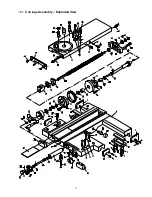
Page 69: ...41 16 1 Carriage Assembly Exploded View ...

Page 70: ...al 100308ZX2172 and lower 1 ZX04506J Wipe Plate serial 100329ZX2173 and higher 1 11 TS 1505071 Hex Socket Cap Screw M10x45 8 12 ZX CA12 Square Cap Bolt M12x70 1 13 ZX CA13 Taper Pin 8x60 mm 2 14 ZX 04729 Clamping Block 1 15 ZX 04730 Locking Plate 1 15a 20151026 Button Support serial 160410ZX3032 and higher 1 15b GB819 M6x12 Countersunk Head Screw serial 160410ZX3032 and higher M6x12 2 16 ZX CA16 P...

Page 71: ... T Slot 2 69 ZX 04732 Pin 1 70 TS 1540081 Hex Nut M12 2 71 ZX 04709 Sleeve 1 GH2280ZX 04701 Sleeve for 2280ZX 1 72 ZX 04304 Pressing Pin 1 73 ZX 04746 G Screw 1 74 ZX 04786 G Set Screw 1 76 TS 1504051 Socket Head Cap Screw M8x22 3 77 ZX 04502 Wipe Plate serial 100308ZX2172 and lower 1 GH2280ZX 04502 Wipe Plate for 2280ZX serial 100308ZX2172 and lower 1 ZX 04502J Wipe Plate serial 100329ZX2173 and ...

Page 72: ...ts List Index No Part No Description Size Qty 1 ZX 09709 Dial 1 2 ZX MS2 Pin B4x8 1 3 ZX 09708 Axle 1 4 ZX 09105 G Stop 1 5 ZX 03302 Sign Plate 1 6 ZX MS6 Nail 3x8 mm 2 7 ZX MS7 Hex Socket Set Screw M6x12 1 8 ZX 09106 Clamping Plate 1 9 ZX MS9 Hex Socket Cap Screw M8x20 2 ...

Page 73: ...45 18 1 Carriage Stop Assembly Exploded View ...

Page 74: ...2 Eccentric Travel Setting Ring 5 7 ZX H66 Flat End Set Screw M6x10 10 8 ZX C08 Pin 4n6x10 5 9 ZX 26703 Locking Key 5 10 ZX 26701A Travel Setting Rod for 1440 1640 1840ZX 1 ZX 26701B Travel Setting Rod for 1460 1660 1860ZX 1 ZX 26701C Travel Setting Rod for 1880 2280ZX 1 11 ZX 26705 G Control Ring 1 12 ZX 26104 G Right Support 1 13 ZX H5 Steel Ball 8 mm 1 14 ZX CS14 Compression Spring 2x8x25 1 15 ...

Page 75: ...47 19 1 Quick Change Tool Post Exploded View ...

Page 76: ...Dial 1 16 ZX 04114 Sleeve 1 17 ZX 04768 Disc Spring 1 18 ZX 04767 G Sleeve 1 19 ZX 04726 G Handle 1 20 ZX 04771 G Lining 1 23 ZX 04752A T Slot Nut 1 24 ZX 04754 Shaft serial 160401ZX3031 and lower 1 1840ZX04801KH Shaft serial 160410ZX3032 and higher 1 29 ZX 04713A Tool Post for 14 models serial 160401ZX3031 and lower 1 ZX 04713B Tool Post for 16 18 22 models serial 160401ZX3031 and lower 1 251 444...

Page 77: ...49 20 1 Tailstock Assembly I Exploded View ...

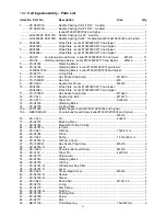
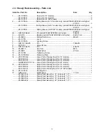
Page 78: ... mm 1 37 ZX 03104 G Lever Sleeve 1 38 ZX 03709 G Lock handle 1 39 ZX A28 Taper Pin 6x55 mm 1 40 TS 1504041 Hex Socket Cap Screw M8x20 4 41 TS 1515031 Hex Socket Cap Screw M8x22 3 42 ZX T42 Pin 10n6x22 1 43 ZX 03302 Sign Plate 1 45 ZX T45 Nail 3x8 mm 4 46 ZX 03105 Nut 1 47 BB 51205 Thrust Ball Bearing 25x47x15 mm 1 48 ZX 03104 Back Cover 1 49 ZX 03103A G Hand Wheel 1 50 ZX 03707 G Lever 1 51 ZX T51...

Page 79: ...51 21 1 Tailstock Assembly II Exploded View ...

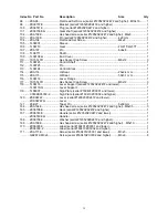
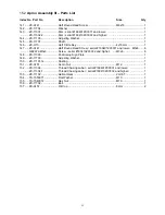
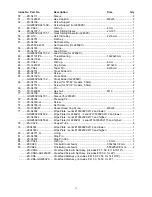
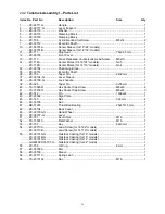
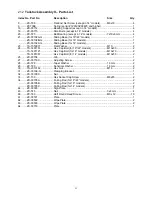
Page 80: ...r M10 2 24 TS 1491151 Hex Cap Bolt for 18 22 models M10x90 2 TS 1491121 Hex Cap Bolt for 16 models M10x70 2 TS 1491081 Hex Cap Bolt for 14 models M10x50 2 25 ZX 03704 Gib 1 27 ZX 03718C Adjusting Screw 2 28 ZX T28 Taper Washer 16 mm 2 29 ZX T29 Spherical Washer 16 mm 2 30 TS 2310162 Hex Nut M16 2 31 ZX 03106 G Clamping Bracket 1 32 ZX 03105C Nut 1 33 ZX T33 Hex Socket Cap Screw M8x85 2 34 ZX 03705...

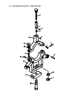
Page 81: ...53 22 1 Steady Rest Assembly Exploded View ...

Page 82: ...119 10n6x55 Pin 10n6x55 1 8 ZX10701 Hinge Screw 1 9 GB119 8n6x55 Pin 8n6x55 1 10 ZX SR10 Hex Nut M20 1 11 ZX SR11 Flat Washer 20 mm 1 12 ZX 10708 Tightening Screw 1 13 ZX 10103D G Clamping Plate 1 14 ZX10101D G Lower Part of Steady Rest for 14 models 1 ZX10101E G Lower Part of Steady Rest for 16 models 1 ZX10101F G Lower Part of Steady Rest for 18 models 1 GH2280ZX 10101 G Lower Part of Steady Res...

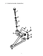
Page 83: ...55 23 1 Follow Rest Assembly Exploded View ...

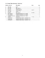
Page 84: ... ZX FR8 Hex Cap Bolt M12x55 2 9 ZX 10102A G Follow Rest Casting for 14 models 1 ZX 10102B G Follow Rest Casting for 16 models 1 ZX 10102C G Follow Rest Casting for 18 models 1 GH2280ZX 10102 G Follow Rest Casting for 22 model 1 10 ZX FR10 Flat Washer 12 mm 2 ZX FRA14 G Follow Rest Assembly 14 includes 1 7 9 ZX FRA16 G Follow Rest Assembly 16 includes 1 7 9 ZX FRA18 G Follow Rest Assembly 18 includ...

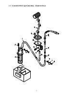
Page 85: ...57 24 1 Coolant Work Light Assembly Exploded View ...

Page 86: ...5 ZX CW05 Hex Nut M6 2 6 ZX 01727 Clip For Rubber Tube 2 7 ZX CW07 Half Round Head Screw M6x16 2 8 ZX 01728 Fitting 1 9 ZX 01729 Flow Pipe 1 10 ZX CW10 Coolant Device 1 ZX CW10 1 Coolant Tap G 3 8 1 11 TS 1514021 Hex Socket Cap Screw M6x16 2 12 TS 1515051 Hex Socket Cap Screw M8x40 2 13 ZX CW13 Lamp Support 1 14 ZX S04 Cross Head Screw M6x14 4 15 ZX CW15 Lamp Frame serial 160401ZX3031 and lower 1 ...

Page 87: ...oss Point Screw Driver 1 16 ZX OP 16 Adjustable Wrench 1 17 ZX OP 17 Round Nut Wrench 1 18 ZX OP 18 Shear Pin 2 21 ZX OP 21 Indicate Bulb serial 160401ZX3031 and lower 110V or 24V 1 ZX HL Indicate Bulb serial 160410ZX3032 and higher XB7 EVF3LC 1 22 ZX OP 22 Taper Piece 1 23 ZX OP 23 Gear 3 5m36T 14 16 22 1 ZX OP 23 Gear 4m36T 18 1 24 ZX OP 24 Leveling Pads 6 25 ZX 250 401 Tool Holder serial 160410...

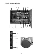
Page 88: ...3A serial 160401ZX3031 and lower JRT1 16A 1 ZX FU5 Fuse 3A serial 160401ZX3031 and lower JRT1 16A 1 ZX FB Fuse Block serial 160401ZX3031 and lower 1 ZX QF2 QF4 Breaker serial 160410ZX3032 and higher DZ47 63 3 9 ZX KM1 A C Contactor for 14 16 18 models 3TB43 1 GH2280ZX KM1 A C Contactor for 22 models 3TB44 1 9a ZX KM2 A C Contactor for 14 16 18 models 3TB43 1 GH2280ZX KM2 A C Contactor for 22 model...

Page 89: ...61 26 2 Electrical Cabinet Breakdown 6 7 8 12 11 10 17 22 21 23 13 9 9a 20 18 3a 1 2 4 19 3 ...

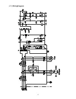
Page 90: ...62 27 0 Wiring Diagram ...

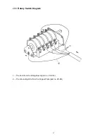
Page 91: ...63 28 0 Rotary Switch Diagram 1 The Cord from the Wiring Board part no ZX XT2 2 The Grounding Wire from the Copper Plate part no ZX XB ...

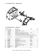
Page 92: ...cessed pan head screw serial 160401ZX3031 and lower M6x12 2 GB70 M6x12 Hex Socket Cap Screw serial 160410ZX3032 and higher M6x12 2 7 ZXS07E Hexagon thin nuts M4 4 8 ZXS08E Plain washers 4 mm 8 9 ZXS09E Cross recessed pan head screws M4x12 4 10 ZXS10E Plain washers 5 mm 4 11 ZXS11E Hexagon socket cap head screws M5x16 4 12 ZX19703E Rest bar 1 13 ZXS13E Slotted set screws M8x10 2 14 ZXS14E Hexagon s...

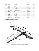
Page 93: ...2m 5a PC 4 1 Nip Φ4 mm 3 5b GB70 M5 10 Hex Socket Cap Screw M5x10 3 6 106095 Tie in SA 4 6 1 7 CL 07 Tie in KC 4 4 8 CL 08 Nylon Pipe Φ4 mm 0 7m 9 CL 09 Spring Sleeve Φ4 mm 0 7m 10 106252 Vitta Tie in CB 4 4 11 106254 Clip Sleeve CS 4 4 12 106255 Plug CP 4 1 13 106411 Connector PJ 6D 1 14 GB70 M5 20 Hex Socket Cap Screw M5x20 2 30 2 Carriage Lubrication Parts List Note This device is installed fro...

Page 94: ...66 427 New Sanford Road LaVergne Tennessee 37086 Phone 800 274 6848 www jettools com ...

Reviews: