64
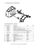
29.1
Safety Guard Cover – Exploded View
29.2
Safety Guard Cover – Parts List
Index No Part No
Description
Size
Qty
1 .......... ZX19701E-G ................. Protection guard ................................................... .................................... 1
2 .......... ZX19501E ..................... Protection guard visual glass ............................... .................................... 1
3 .......... ZX19704E ..................... Fixing rod ............................................................. .................................... 1
4 .........
ZXS04E
..........................
Handle (serial #160401ZX3031 and lower)
..........
Z96-6
............................ 1
............
A=90 Black
....................
Handle (serial #160410ZX3032 and higher)
........ ...................................... 1
5 ..........
ZX-S05E
........................
Plain washer (serial #160401ZX3031 and lower)……6 mm
...................... 2
6 ..........
ZX-S06E
........................
Cross-recessed pan head screw (serial #160401ZX3031 and lower)
........
............ ........................................ .................................................................................
M6x12
........................... 2
............
GB70- M6x12
................
Hex Socket Cap Screw (serial #160410ZX3032 and higher)
......................
............ ........................................ .................................................................................
M6x12
........................... 2
7 .......... ZXS07E ......................... Hexagon thin nuts ................................................ M4 ............................... 4
8 .......... ZXS08E ......................... Plain washers ....................................................... 4 mm ........................... 8
9 .......... ZXS09E ......................... Cross recessed pan head screws ........................ M4x12 ......................... 4
10 ........ ZXS10E ......................... Plain washers ....................................................... 5 mm ........................... 4
11 ......... ZXS11E ......................... Hexagon socket cap head screws ....................... M5x16 ......................... 4
12 ........ ZX19703E ..................... Rest bar ................................................................ .................................... 1
13 ........ ZXS13E ......................... Slotted set screws ................................................ M8x10 ......................... 2
14 ........ ZXS14E ......................... Hexagon socket cap head screws ....................... M6x35 ......................... 4
15 ........ ZXS15E ......................... Hexagon socket set screws ................................. M8x16 ......................... 1
16 ........ GH1440A19101E .......... Switch box ............................................................ .................................... 1
19 ........ ZX19702E ..................... Shaft ..................................................................... .................................... 1
21 ........ ZXS21E ......................... Nut ........................................................................ M8 ............................... 1
(Note: This device is installed from serial #110825ZX2338)
Summary of Contents for GH-1440ZX
Page 26: ...26 T H R E A D I N G C H A R T I N I N C H ...
Page 27: ...27 m m M E T R I C T H R E A D I N G C H A R T M P M O D U L E P I T C H ...
Page 31: ...3 1 1 Stand Assembly Exploded View ...
Page 34: ...6 2 1 Brake Assembly Exploded View ...
Page 36: ...8 3 1 Bed Assembly Exploded View ...
Page 39: ...11 4 1 Headstock Assembly I Exploded View ...
Page 43: ...15 5 1 Headstock Assembly II Exploded View ...
Page 46: ...18 6 1 Headstock Assembly III Exploded View ...
Page 48: ...20 7 1 Headstock Assembly IV Exploded View ...
Page 50: ...22 8 1 Change Gear Box Assembly I Exploded View ...
Page 52: ...24 9 1 Change Gear Box Assembly II Exploded View ...
Page 54: ...26 10 1 Quick Change Gear Box I Exploded View ...
Page 57: ...29 11 1 Quick Change Gear Box II Exploded View ...
Page 59: ...31 12 1 Quick Change Gear Box III Exploded View ...
Page 61: ...33 13 1 Apron Assembly I Exploded View ...
Page 64: ...36 14 1 Apron Assembly II Exploded View ...
Page 67: ...39 15 1 Apron Assembly III Exploded View ...
Page 69: ...41 16 1 Carriage Assembly Exploded View ...
Page 73: ...45 18 1 Carriage Stop Assembly Exploded View ...
Page 75: ...47 19 1 Quick Change Tool Post Exploded View ...
Page 77: ...49 20 1 Tailstock Assembly I Exploded View ...
Page 79: ...51 21 1 Tailstock Assembly II Exploded View ...
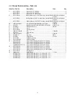
Page 81: ...53 22 1 Steady Rest Assembly Exploded View ...
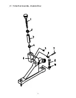
Page 83: ...55 23 1 Follow Rest Assembly Exploded View ...
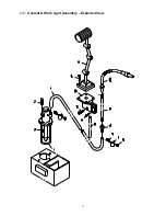
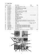
Page 85: ...57 24 1 Coolant Work Light Assembly Exploded View ...
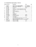
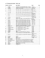
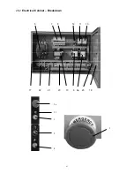
Page 89: ...61 26 2 Electrical Cabinet Breakdown 6 7 8 12 11 10 17 22 21 23 13 9 9a 20 18 3a 1 2 4 19 3 ...
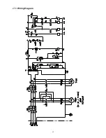
Page 90: ...62 27 0 Wiring Diagram ...
Page 94: ...66 427 New Sanford Road LaVergne Tennessee 37086 Phone 800 274 6848 www jettools com ...

