17
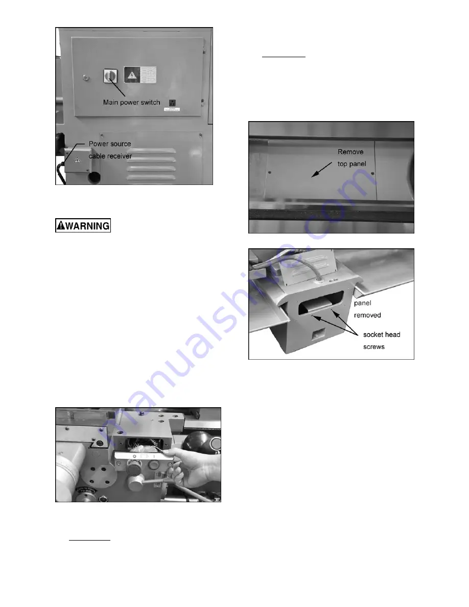
Figure 17 – Power input
10.1
Conversion to 460 Volt Operation
Disconnect machine from
power source. Failure to do so may cause
serious or fatal injury.
Wiring diagrams are located at the relevant areas
on the machine; each diagram is also provided in
section 17.0
. Should discrepancies exist, the
diagrams on the machine take precedence.
There are four steps involved in converting to 460
volt power:
1.
Main Motor:
Open lower panel at rear of lathe
beneath the gearbox, and change the wires in
the junction box on the main motor, according
to the diagram on the junction box cover.
2.
Rapid Feed Motor:
Remove the control panel
on the saddle (Figure 18) to rewire the rapid
feed motor. Change the leads according to the
wiring diagram in
sect. 17.0.
It is not
necessary to pull out the rapid feed motor
for voltage conversion.
Figure 18 – Rapid feed motor wire access
3.
Coolant Pump:
GH-2680ZH:
Open access panel on the base
at the tailstock end. Change wires in coolant
pump junction box according to diagram on the
junction box cover.
GH-26120ZH:
1) Remove top panel inside the bed (Figure
19).
2) Remove rear panel on center stand then
remove the two socket head screws
(Figure 20) that secure the plate on which
the coolant pump is mounted.
Figure 19 –Coolant pump access (GH-26120ZH)
Figure 20 – Coolant pump access (GH-26120ZH)
3) Tilt the plate until you can reach the
coolant pump junction box through the top
opening in the bed. Follow the diagram on
the coolant pump to change the leads.
4) Properly orient the pump, and secure the
plate with the two screws.
5) Close both covers.
4.
Transformer:
Open electrical box on rear of
machine on the headstock side. Switch wire
from 230V terminal to 460V terminal as
outlined on the transformer label. See Figure
21.
Voltage conversion is now complete. Close the
electrical box before operating the lathe.
Summary of Contents for GH-26120ZH
Page 34: ...34 18 0 Change Gear Diagram Figure 54 ...
Page 35: ...35 This page intentionally left blank ...
Page 40: ...4 1 1 Bed Assembly I Exploded View ...
Page 41: ...5 1 2 Bed Assembly I for 120 ZH only Exploded View ...
Page 44: ...8 2 1 Bed Assembly II Exploded View ...
Page 45: ...9 2 2 Bed Assembly II for 120 ZH only Exploded View ...
Page 48: ...12 3 1 Headstock Assembly I Exploded View Ⅲ Ⅳ Ⅴ Ⅶ Ⅵ Ⅱ Ⅰ Ⅱb Ⅶb ZⅡ ZⅠ ZⅡ ...
Page 51: ...15 4 1 Headstock Assembly II Exploded View ...
Page 54: ...18 5 1 Headstock Assembly III Exploded View ...
Page 56: ...20 6 1 Headstock Assembly IV Exploded View Ⅰ Ⅱb Ⅱ Ⅲ Ⅳ Ⅴ ...
Page 59: ...23 7 1 Headstock Assembly V Exploded View Ⅶ Ⅶb Ⅵ ...
Page 62: ...26 9 1 Gear Box Assembly I Exploded View Ⅱ Ⅲ Ⅰ ...
Page 64: ...28 10 1 Gear Box Assembly II Exploded View ...
Page 67: ...31 11 1 Gear Box Assembly III Exploded View ...
Page 70: ...34 12 1 Brake Assembly Exploded View ...
Page 72: ...36 13 1 Saddle and Cross Slide Assembly Exploded View ...
Page 75: ...39 14 1 Tool Post and Compound Rest Assembly Exploded View ...
Page 77: ...41 15 1 Apron Assembly I Exploded View Ⅱ Ⅹ Ⅱ Ⅲ Ⅷ Ⅹ Ⅸ Ⅹ Ⅳ Ⅰ Ⅹ Ⅰ Ⅵ Ⅲ Ⅴ Ⅶ ...
Page 80: ...44 16 1 Apron Assembly II Exploded View Ⅺ Ⅹ Ⅲ Ⅻ Ⅸ Ⅹ Ⅶ ...
Page 83: ...47 17 1 Apron Assembly III Exploded View Ⅰ Ⅱ Ⅴ Ⅲ Ⅳ Ⅵ ...
Page 85: ...49 18 1 Apron Assembly IV Exploded View ...
Page 87: ...51 19 1 Tailstock Assembly I Exploded View ...
Page 89: ...53 20 1 Tailstock Assembly II Exploded View ...
Page 91: ...55 21 1 Steady Rest Assembly Small and Large Exploded View ...
Page 95: ...59 24 1 Travel Stop Assembly Exploded View ...
Page 100: ...64 27 2 Electrical Diagram ...


