13
3.2
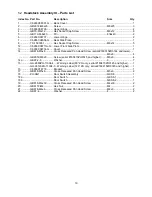
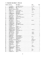
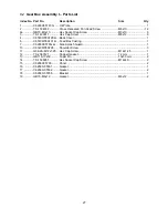
Headstock Assembly I – Parts List
Index No. Part No.
Description
Size
Qty
1 ............... C6266C02502-G ...... Headstock Cover ................................................. .................................... 1
3 ............... C6140W02835 ......... Flat Head Countersunk Screw ............................. .................................... 1
4 ............... TS-1505051 ............. Hex Socket Cap Screw ........................................ M10x35 ....................... 8
5 ............... GB6172-M12 ............ Hex Nut ................................................................ M12 ............................. 2
6 ............... C6266C02768 .......... Braking Belt Support ............................................ .................................... 1
7 ............... GB65-M6x10 ............ Slotted Socket Cap Screw ................................... M6x10 ......................... 4
8 ............... C6266C02767 .......... Braking Belt .......................................................... .................................... 1
9 ............... GB867-3x10 ............. Cup Head Rivet .................................................... 3x10 mm ..................... 3
10 ............. C6266C02503 .......... Braking Friction Disc ............................................ .................................... 1
11 ............. GB119-6n6x14 ......... Pin ........................................................................ 6n6x14 mm ................. 1
12 ............. C6266C02770 .......... Braking Belt Support ............................................ .................................... 1
13 ............. C6266C02769 .......... Shaft ..................................................................... .................................... 1
14 ............. GB3452.1-30x2.65 ... O-Ring .................................................................. 30x2.65 mm ................ 1
15 ............. R51-2-M27x1.5 ........ Oil Glass ............................................................... M27x1.5 ...................... 2
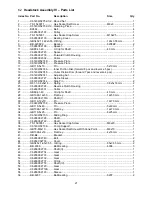
16 ............. GB818-M3x4 ............ Cross Recessed Pan Head Screw (serial #160315ZH0144 and lower) .....
................. ................................. ............................................................................. M3x4 ......................... 14
................. GB2672-M3x6 .......... Screw (serial #160415ZH0145 and higher) ......... M3x6 ......................... 14
17 ............. C6266C02306 .......... Sign Label– Oil Level (serial #160315ZH0144 and lower) ....................... 1
................. C6266C02306-1 ....... Sign Label– Oil Level (serial #160415ZH0145 and higher) ...................... 1
18 ............. C6266C02101-G ...... Headstock ............................................................ .................................... 1
19 ............. GB5782-M20x75 ...... Hexagon Head Bolt .............................................. M20x75 ....................... 3
19a ........... GB97.2-20 ................ Washer ................................................................. 20 mm ......................... 3
20 ............. C6266C02125 .......... Fork ...................................................................... .................................... 1
20a ........... C6266C02721A ....... Control Shaft ........................................................ .................................... 1
21 ............. GB881-8x40 ............. Pin ........................................................................ 8x40 mm ..................... 1
21a ........... GB6172-M8 .............. Hex Nut ................................................................ M8 ............................... 1
22 ............. GB71-M12x30 .......... Slotted Set Screw ................................................ M12x30 ....................... 1
23 ............. Q81-1-1.6x8x70 ....... Spring ................................................................... 1.6x8x70 ..................... 1
24 ............. SB-10MM ................. Steel Ball .............................................................. 10 mm ......................... 1
25 ............. C6266C02130 .......... Bushing ................................................................ .................................... 1
26 ............. GB3452.1-38.7x3.55 O-Ring .................................................................. 38.7x3.55 mm ............. 1
27 ............. GB818-M6x16 .......... Cross Head Screw ............................................... M6x16 ......................... 3
27a ........... GB97.2-6 .................. Washer ................................................................. 6 mm ........................... 3
27b ........... GB73-M8x10 ............ Slotted Set Screw ................................................ M8x10 ......................... 1
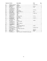
28 ............. C6266C02757-G ...... Cover .................................................................... .................................... 1
29 ............. GB3452.1-26.5x2.65 O-Ring .................................................................. 26.5x2.65 mm ............. 1
29a .......... GB73-M10x10 .......... Slotted Set Screw ................................................ M10x10 ....................... 2
30 ............. C6266C02761 .......... Control Shaft ........................................................ .................................... 1
31 ............. C6266C02128 .......... Fork ...................................................................... .................................... 1
32 ............. C6266C02124 .......... Fork ...................................................................... .................................... 1
33 ............. C6266C02120 .......... Fork ...................................................................... .................................... 1
34 ............. C6266C02762 .......... Control Shaft ........................................................ .................................... 1
35 ............. C6140W02141-G ..... Front Cover .......................................................... .................................... 1
36 ............. C6140W02711 ......... Screw ................................................................... .................................... 3
37 ............. GB5782-M16x80 ...... Hexagon Head Bolt .............................................. M16x80 ....................... 2
37a ........... GB97.2-16 ................ Washer ................................................................. 16 mm ......................... 3
38 ............. C6140W02831 ......... Nut ........................................................................ .................................... 1
40 ............. C6140W02832 ......... Drain Pipe ............................................................ .................................... 1
41 ............. C6140W02833 ......... Clamping Plate ..................................................... .................................... 1
42 ............. TS-1494052 ............. Hex Cap Screw .................................................... M16x60 ....................... 1
43 ............. C6266C02303 .......... Sign Label (serial #160315ZH0144 and lower) ... .................................... 1
................. C6266C02303-1 ....... Sign Label (serial #160415ZH0145 and higher) .. .................................... 1
44 ............. C6140W02143 ......... Sliding Block......................................................... .................................... 1
45 ............. GB119-N6x20 .......... Pin ........................................................................ n6x20 mm ................... 1
46 ............. C6140W02129 ......... Rocker .................................................................. .................................... 1
Summary of Contents for GH-26120ZH
Page 34: ...34 18 0 Change Gear Diagram Figure 54 ...
Page 35: ...35 This page intentionally left blank ...
Page 40: ...4 1 1 Bed Assembly I Exploded View ...
Page 41: ...5 1 2 Bed Assembly I for 120 ZH only Exploded View ...
Page 44: ...8 2 1 Bed Assembly II Exploded View ...
Page 45: ...9 2 2 Bed Assembly II for 120 ZH only Exploded View ...
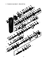
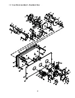
Page 48: ...12 3 1 Headstock Assembly I Exploded View Ⅲ Ⅳ Ⅴ Ⅶ Ⅵ Ⅱ Ⅰ Ⅱb Ⅶb ZⅡ ZⅠ ZⅡ ...
Page 51: ...15 4 1 Headstock Assembly II Exploded View ...
Page 54: ...18 5 1 Headstock Assembly III Exploded View ...
Page 56: ...20 6 1 Headstock Assembly IV Exploded View Ⅰ Ⅱb Ⅱ Ⅲ Ⅳ Ⅴ ...
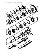
Page 59: ...23 7 1 Headstock Assembly V Exploded View Ⅶ Ⅶb Ⅵ ...
Page 62: ...26 9 1 Gear Box Assembly I Exploded View Ⅱ Ⅲ Ⅰ ...
Page 64: ...28 10 1 Gear Box Assembly II Exploded View ...
Page 67: ...31 11 1 Gear Box Assembly III Exploded View ...
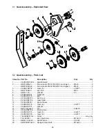
Page 70: ...34 12 1 Brake Assembly Exploded View ...
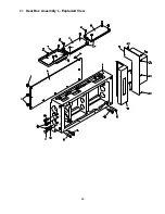
Page 72: ...36 13 1 Saddle and Cross Slide Assembly Exploded View ...
Page 75: ...39 14 1 Tool Post and Compound Rest Assembly Exploded View ...
Page 77: ...41 15 1 Apron Assembly I Exploded View Ⅱ Ⅹ Ⅱ Ⅲ Ⅷ Ⅹ Ⅸ Ⅹ Ⅳ Ⅰ Ⅹ Ⅰ Ⅵ Ⅲ Ⅴ Ⅶ ...
Page 80: ...44 16 1 Apron Assembly II Exploded View Ⅺ Ⅹ Ⅲ Ⅻ Ⅸ Ⅹ Ⅶ ...
Page 83: ...47 17 1 Apron Assembly III Exploded View Ⅰ Ⅱ Ⅴ Ⅲ Ⅳ Ⅵ ...
Page 85: ...49 18 1 Apron Assembly IV Exploded View ...
Page 87: ...51 19 1 Tailstock Assembly I Exploded View ...
Page 89: ...53 20 1 Tailstock Assembly II Exploded View ...
Page 91: ...55 21 1 Steady Rest Assembly Small and Large Exploded View ...
Page 95: ...59 24 1 Travel Stop Assembly Exploded View ...
Page 100: ...64 27 2 Electrical Diagram ...


