15
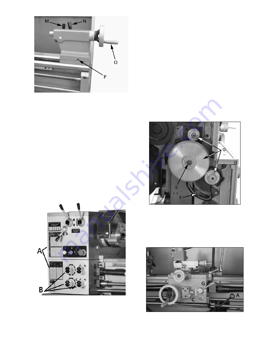
Figure 9-4
10.0
Operation
10.1
Break-in procedure
During manufacturing and testing, this lathe has
been operated in the low RPM range for three
hours.
To allow time for the gears and bearings to break-
in and run smoothly, do not run the lathe above
755 RPM for the first six hours of operation and
use.
10.2
Feed and thread selection
1. Reference the feed and thread table (A, Figure
10-1).
2. Move knobs and handle (B, Figure 10-1) to
appropriate positions.
Figure 10-1
10.3
Change gear replacement
Note
: The 24T, 127T, and 48T gears are installed
in the end gear compartment when delivered from
the factory. This combination will cover most inch
feeds and threads under normal circumstances.
The additional gears found in the toolbox are used
for some metric threads and feeds.
1. Disconnect machine from power source.
2. Open the cover on left end of headstock.
3. Loosen hex nuts (E/F, Figure 10-2). Move
quadrant out of the way.
4. Change gears (G, Figure 10-2) to match feed
and thread chart.
5. Thoroughly clean and install new gears.
6. Move quadrant so the large gear meshes with
the smaller gears, and tighten to secure in
place. Note: Make sure there is backlash of
0.002” – 0.003” between gears. Setting gears
too tight will cause excessive noise and wear.
7. Close cover and connect machine to power
source.
Figure 10-2
10.4
Automatic feed operation and
feed changes
1. Move the forward/reverse selector (A, Figure
10-3) up or down depending on desired
direction.
Figure 10-3
Summary of Contents for GHB-1236
Page 18: ...18 12 0 Thread and feed chart Table 3 ...
Page 20: ...20 13 2 1 Headstock Assembly Exploded View ...
Page 21: ...21 ...
Page 24: ...24 13 3 1 Gearbox Assembly Exploded View ...
Page 25: ...25 ...
Page 28: ...28 13 4 1 Apron Assembly Exploded View ...
Page 31: ...31 13 5 1 Cross Slide Assembly Exploded View ...
Page 33: ...33 13 6 1 Compound Rest Assembly Exploded View ...
Page 36: ...36 13 7 1 Tailstock Assembly Exploded View ...
Page 39: ...39 13 9 1 Feed Rod Assembly Exploded View ...
Page 41: ...41 13 10 2 Motor and Change Gear Enclosure Exploded View ...
Page 43: ...43 13 11 1 Stand Brake Coolant Pump Exploded View ...
Page 44: ...44 ...
Page 46: ...46 13 12 1 Electrical Box Assembly Exploded View ...
Page 48: ...48 13 13 1 Steady Rest and Follow Rest Parts List ...
Page 51: ...51 13 15 1 Accessories Exploded View ...
Page 53: ...53 14 0 Wiring Diagram for GHB 1236 ...
Page 55: ...55 This page intentionally left blank ...
Page 56: ...56 427 New Sanford Road LaVergne Tennessee 37086 Phone 800 274 6848 www jettools com ...


