13
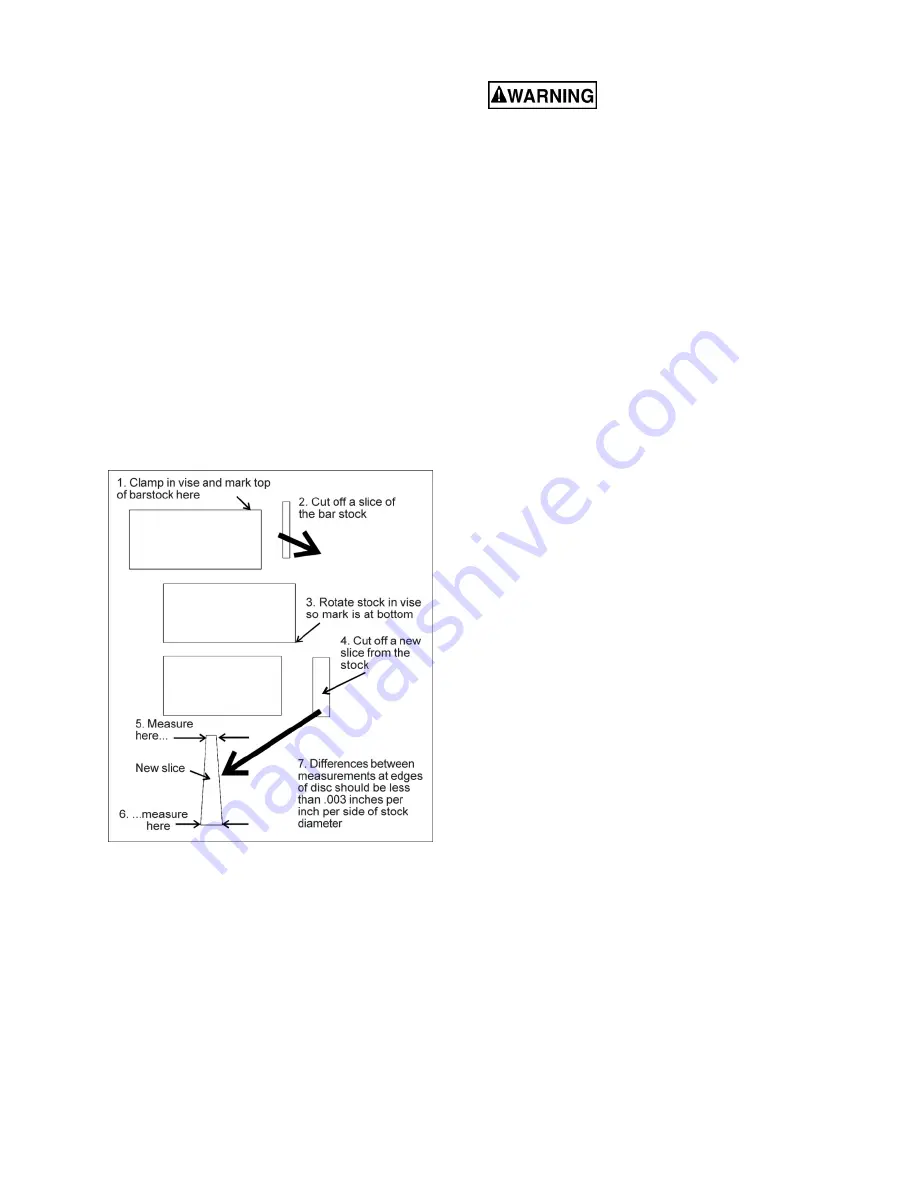
1. With bar stock securely clamped in the vise,
make a cut through the bar stock (see Figure 7-
4).
2. Mark the top of the bar stock.
3. Move the bar stock about 1/4-inch past the
blade to prepare for a second cut.
4. Rotate the bar stock 180 degrees so that your
mark is now at the bottom of the cut.
5. Make a cut through the bar stock.
6. Use a micrometer to measure the thickness
variation of the disk which has been cut from the
bar stock. Measure at top and bottom of disk.
The saw blade can be considered correctly adjusted
when the variation measure is no more than 0.012
inch across the face of the disk.
If you do not have a piece of 2-inch bar stock
available for a test cut, use a larger diameter test
piece rather than a smaller one. The maximum
thickness variation on any test piece should be no
more than 0.003 inch, per side, per inch of stock
diameter.
Figure 7-4: test cut
7.7
Changing blade speeds
Disconnect machine from
power source before changing belt position.
Failure to comply may cause serious injury.
1. Disconnect machine from power source.
2. Open pulley cover.
3. Support motor with one hand while loosening
lock handle (C, Figure 5-3). Lower motor gently.
4. Position belt in grooves according to speed
selection chart on pulley cover. A similar chart
is found in
sect 12.0
.
5. Tension the belt by pushing up motor and
tightening lock handle. Correct tension is
achieved when finger pressure on the belt
midway between the two pulleys causes
approximately 1/2" deflection.
6. Close pulley cover and fasten.
7.8
Bow weight adjustment
Bow weight has been properly set by the
manufacturer and should not require attention. If
future adjustment becomes necessary, due to part
replacement or other contingency, proceed as
follows:
1. Disconnect machine from power source.
2. Raise bow to allow sufficient room for the
following procedure, and use hydraulic valve
knob to keep it in raised position.
3. Place one end of a fish-type scale under the
blade tension handle and lift the bow with the
other end of the scale. The scale should
indicate approximately 18-to-20 lbs. for the
HBS-916. For the HBS-1018, it should indicate
22-to-24 lbs.
4. Adjust tension by loosening one nut on the C-
bolt (L, Figure 7-6) and tightening the other.
Tighten nut and retest the weight.
7.9
Vise adjustments
7.9.1
General procedure
1. Place workpiece between vise jaws with
required amount to be cut-off extending past
blade. (Figure 7-5 shows recommended
positioning of various workpiece shapes within
the vise.)
Summary of Contents for HBS-1018
Page 21: ...21 14 1 1 HBS 916 HBS 1018 Bed and Base Assembly Exploded View ...
Page 22: ...22 14 1 2 HBS 916 Bow Assembly Exploded View ...
Page 23: ...23 14 1 3 HBS 1018 Bow Assembly Exploded View ...
Page 30: ...30 14 2 1 HBS 916 HBS 1018 Gear Speed Reducing Box Exploded View ...
Page 32: ...32 5 0 Electrical Connections 15 1 Electrical Connections HBS 916 only ...
Page 33: ...33 15 2 Electrical Connections HBS 1018 only ...
Page 35: ...35 ...
Page 36: ...36 427 New Sanford Road LaVergne Tennessee 37086 Phone 800 274 6848 www jettools com ...


