11
Adjustments
Vise
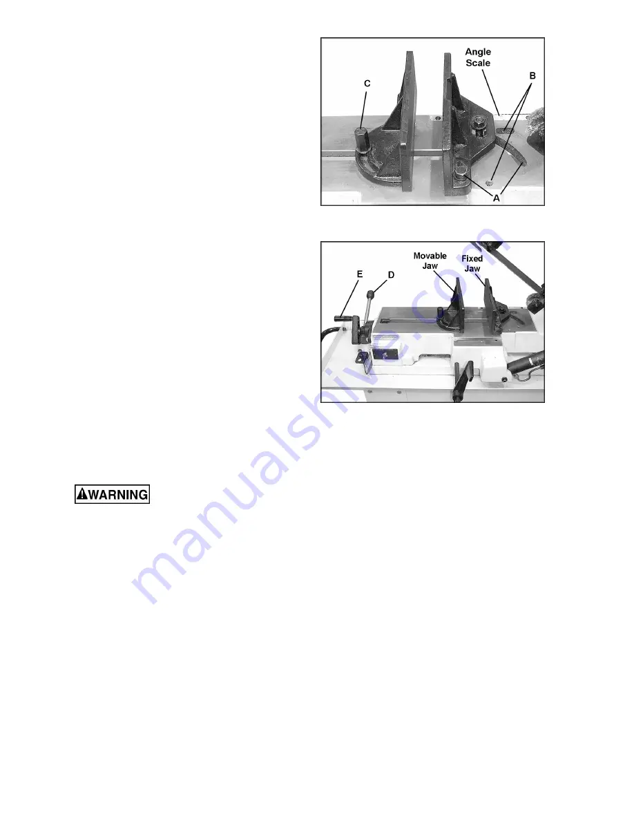
There are two sets of holes in the bed to mount
the right jaw. The inner hole and slot (A, Figure
10) are used for miter cuts. The outer hole and
slot (B, Figure 10) are used for square, or 90°
cuts. Figure 10 shows the vise located in the “A”
position for miter cuts.
Use only position “A” for miter cuts. If the “A”
position is used for square cuts, it leaves more
blade exposed to the right of the jaw.
Squaring Vise to Blade
1. To set up for square cutting, move the right
jaw to “B” position (Figure 10). Place a
machinist’s square on the bed against the
blade and the right vise jaw. The square
should lie along the entire length of the jaw
and blade without a gap.
2. If adjustment is necessary, slightly loosen
the front screw on the right jaw. Loosen the
hex nut at the center of the right jaw and
adjust jaw so the square lines up properly.
3. Re-tighten the hex nut and the front screw.
4. Loosen the handle (C, Figure 10) on the left
jaw. Move the left jaw until it contacts flush
with the right jaw.
5. Tighten the handle (C, Figure 10). The vise
is now set for square cuts.
Positioning the Vise
Keep hands away from blade
while adjusting the vise.
1. The workpiece is placed against the fixed
jaw, which has already been squared (see
“Squaring Vise to Blade”), or has been
locked at the appropriate angle (see “Miter
Cuts”).
2. The vise has a quick-release feature which
allows fast positioning of the movable jaw
against the workpiece and then a final
tightening with the handle. Lift up on the
quick release lever (D, Figure 11), then
push the movable jaw by hand until it
contacts the workpiece.
3. Push down the quick release lever (D,
Figure 11).
4. Turn the lead screw handle (E, Figure 11)
clockwise to continue the tightening process
of the movable jaw until the workpiece is
securely clamped.
Figure 10
(fixed jaw shown in “A” position for mitering)
Figure 11
Summary of Contents for HBS-814GH
Page 20: ...20 Base Assembly ...
Page 21: ...21 Bow Assembly 202 ...
Page 26: ...26 Gear Box Assembly ...
Page 28: ...28 Electrical Control Box Assembly ...
Page 30: ...30 Electrical Connections ...
Page 31: ...31 ...


