9
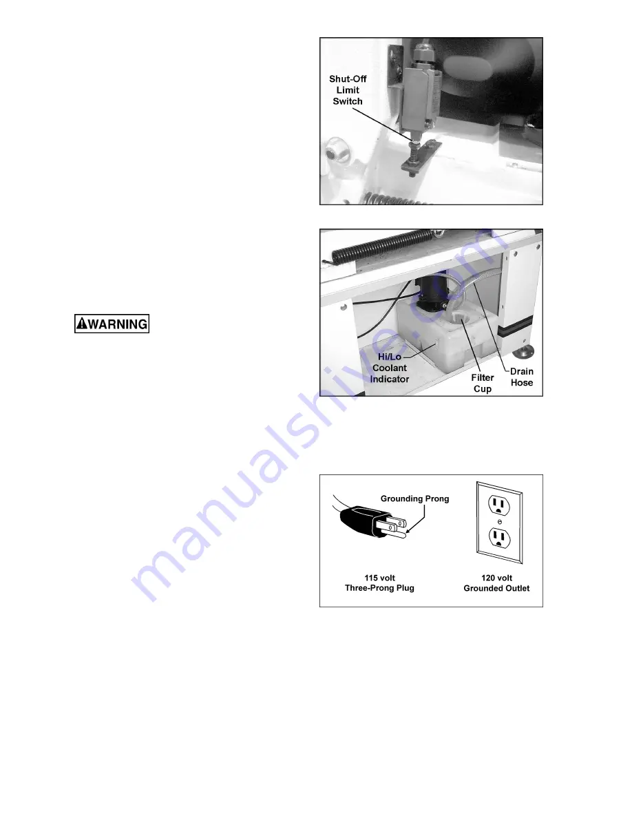
Shut-Off Switch
Remove the screw and hex nuts which held the
bow to the base during shipment. These should
be retained in case of future transportation of
the Band Saw.
The screw below the limit switch, shown in
Figure 4, has been pre-set at the factory so that
the switch will contact the screw and stop the
blade after each cutting operation.
Coolant Hose
Before operating, the coolant drain hose (Figure
5) must be connected to the coolant pan and the
other end of the hose placed into the filter cup in
the tank as shown.
The hose from the coolant pump is attached to a
valve which should be inserted into the hole on
the guide assembly (see Figure 17).
Grounding Instructions
Electrical connections must
be made by a qualified electrician in
compliance with all relevant codes. This
machine must be properly grounded to help
prevent electrical shock and possible fatal
injury.
This machine must be grounded. In the event of
a malfunction or breakdown, grounding provides
a path of least resistance for electric current to
reduce the risk of electric shock.
This band saw is pre-wired for 115 volt and is
equipped with an electric cord having an
equipment-grounding conductor and a
grounding plug similar to that shown in Figure 6.
The plug must be inserted into a matching outlet
that is properly installed and grounded in
accordance with all local codes and ordinances.
Do not modify the plug provided. If it will not fit
the outlet, have the proper outlet installed by a
qualified electrician.
Improper connection of the equipment-
grounding conductor can result in a risk of
electric shock. The conductor, with insulation
having an outer surface that is green with or
without yellow stripes, is the equipment-
grounding conductor. If repair or replacement of
the electric cord or plug is necessary, do not
connect the equipment-grounding conductor to a
live terminal.
Check with a qualified electrician or service
personnel if the grounding instructions are not
completely understood, or if in doubt as to
whether the machine is properly grounded.
Figure 4
Figure 5
Figure 6
Summary of Contents for HBS-814GH
Page 20: ...20 Base Assembly ...
Page 21: ...21 Bow Assembly 202 ...
Page 26: ...26 Gear Box Assembly ...
Page 28: ...28 Electrical Control Box Assembly ...
Page 30: ...30 Electrical Connections ...
Page 31: ...31 ...


