background image


12 

Maintenance 

For  safety,  turn  the  switch  to  OFF  and  remove 
plug  from  the  power  source  outlet  before 
adjusting  and  maintaining  the  bench  grinder.  If 
the  power  cord  is  worn,  cut  or  damaged  in  any 
way, have it replaced immediately. 
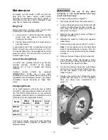
Ring Test 

Before  replacing  a  grinding  wheel,  perform  this 
simple test on the replacement wheel: 

1.  Loop  a  piece  of  string  through  the  grinding 

wheel  hole  and  suspend  the  wheel  by 
holding up the string. 

2.  Tap the wheel with a piece of scrap wood or 

a wooden dowel. 

A  good  wheel  will  "ring";  a  defective  wheel  will 
"thud".  Discard  any  wheel  that  does  not  "ring". 
An internal defect may not be apparent by visual 
inspection  alone.  The  ring  test  may  uncover  an 
internal crack or void. 

Care of Grinding Wheel 

In  normal  use,  grinding  wheels  may  become 
cracked,  grooved,  rounded  at  the  edges, 
chipped,  out  of  true  or  loaded  with  foreign 
material. 

Cracked 

wheels 

should 

be 

replaced 

IMMEDIATELY.  While  any  of  the  other 
conditions can be remedied with a dressing tool 
(available at most hardware stores), new wheels 
sometimes  require  dressing  to  make  them 
round. 

Changing Wheels 

If  you  must  replace  a  wheel  be  sure  to  obtain 
one with a safe rated speed at least as high as 
the 

NO


LOAD RPM 

marked  on  the  grinder's 

nameplate. Refer to Table 2 to determine correct 
dimensions for the replacement wheel. 

Model 

Wheel 

Diameter 

Maximum 

Width 

Center 

Hole 

JBG-6A 

6" 

3/4" 

1/2" 

JBG-8A 

8" 

1" 

5/8" 

JBG-10A 

10" 

1" 

1" 

Table 2 

Your  bench  grinder  will  accept  most  polishing 
and  buffing  wheels  available  at  dealers  and 
hardware stores. 

  The  use  of  any  other 

accessory  is  not  recommended  and  may 
result in serious injury! 

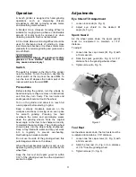
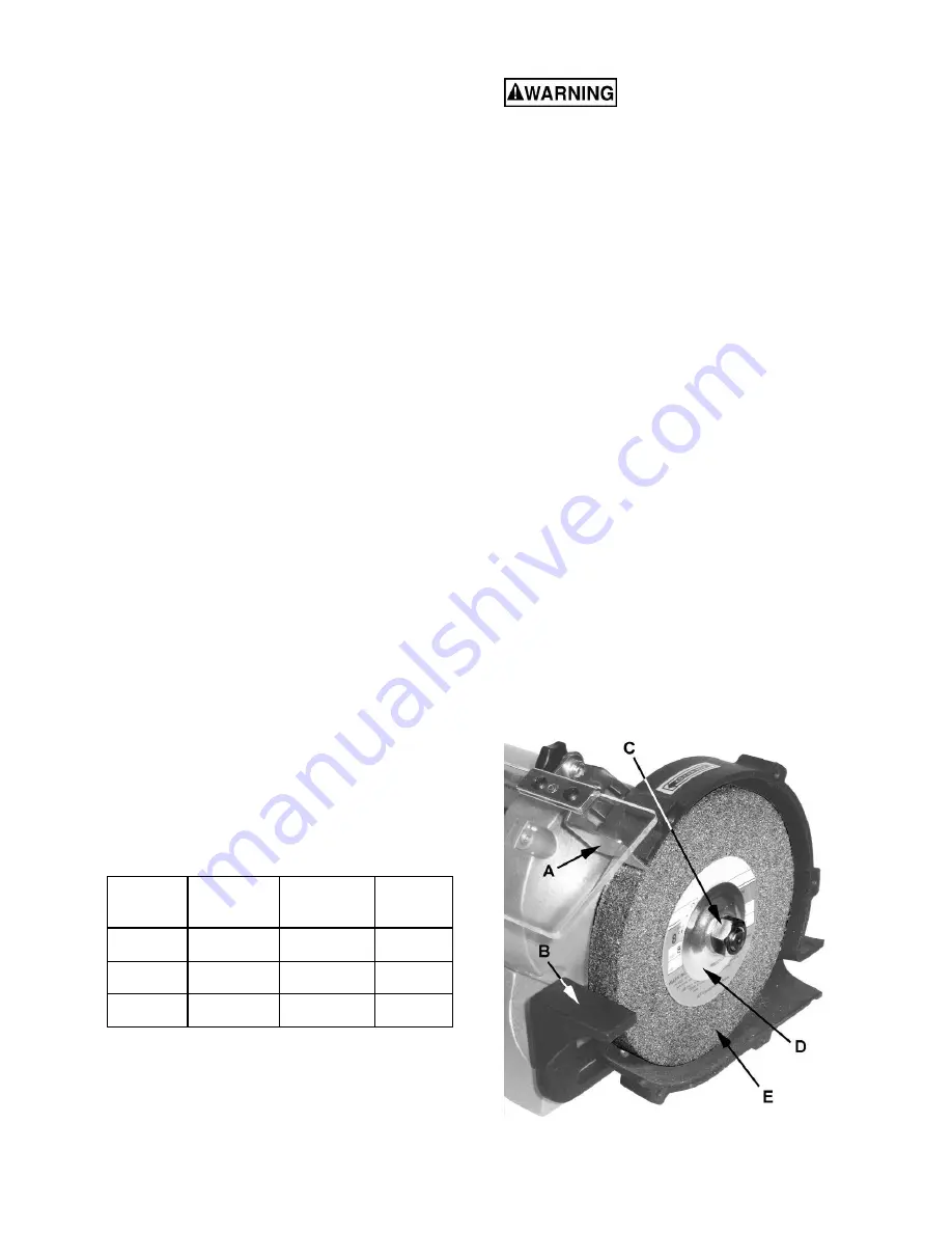
To change a wheel (refer to Figure 4): 

1.  Disconnect grinder from the power source. 

2.  Loosen the 

spark guard

 (A) and 

tool rest

 (B) 

(refer to the Adjustment section on page 11) 
and  move  the  spark  guard  and  tool  rest 
away from the wheel. 

3.  Remove the guard cover using a Phillips or 

flathead screwdriver. 

4.  Stabilize  the  wheel  by  holding  the  opposite 

wheel firmly. 

5.  Unscrew the 

wheel nut 

(C) with a 1" wrench. 

Note

: Turn the locking nut on the right-hand 

wheel  counterclockwise  to  loosen.  Turn  the 
locking nut on the left-hand wheel clockwise 
to loosen. 

6.  Remove the outer flange (D) and wheel (E). 

7.  Clean  flanges.  Check  the  flanges  to  make 

sure they are flat. Wheel flanges that are not 
flat will cause the wheel to wobble. 

8.  Put the inner flange, wheel (E), outer flange 

(D) and nut (C) on the shaft. Tighten the nut. 
Do  not  over  tighten.  This  may  cause  the 
wheel to crack. 

9.  Replace  the  guard  cover.  Adjust  the  spark 

guards  and  tool  rests  to  a  1/16"  clearance 
from  the  wheel  (see 

Adjustments on 

page 

11

)


Figure 4 

Summary of Contents for JBG-8A

Page 1: ...G Series Bench Grinders Models JBG 6A JBG 8A JBG 10A Model JBG 8A shown JET 427 New Sanford Road LaVergne Tennessee 37086 Part No M 577101 Ph 800 274 6848 Revision M 06 2019 www jettools com Copyright...

Page 2: ...nal action needed JET has Authorized Service Centers located throughout the United States For the name of an Authorized Service Center in your area call 1 800 274 6846 or use the Service Center Locato...

Page 3: ...11 Precautions 11 Adjustments 11 Eye Shield Tilt Adjustment 11 Spark Guard 11 Tool Rest 11 Maintenance 12 Ring Test 12 Care of Grinding Wheel 12 Changing Wheels 12 Grinding Wheels 13 Wire Wheel Brush...

Page 4: ...cting the machine to the power supply 13 Make certain the machine is properly grounded 14 Make all machine adjustments or maintenance with the machine unplugged from the power source 15 Remove adjusti...

Page 5: ...ver leave the machine running unattended Turn the power off and do not leave the machine until it comes to a complete stop 34 Remove loose items and unnecessary work pieces from the area before starti...

Page 6: ...10A Stock Number 577101 577102 577103 Overall Dimension L x H x D in 18 x 10 1 2 x 8 1 2 19 x 12 1 2 x 10 24 1 2 x 12 1 4 x 13 Wheel Size D x W x Bore in 6 x 3 4 x 1 2 8 x 1 x 5 8 10 x 1 x 1 Wheels In...

Page 7: ...ardware 1 ea Bracket Left A 2 ea Lock Knob B 1 ea Bracket Right C 1 ea Spark Guard Left D 2 ea 1 4 x 1 2 Screw E 1 ea Spark Guard Right F 2 ea Eye Shield Bracket Plate G 4 ea 5 16 x 3 4 Hex Cap Screw...

Page 8: ...y Do not operate this grinder without all guards and shields in place and in working order Failure to comply may cause serious injury Chipped or cracked wheels can break up and cause serious damage to...

Page 9: ...t tool rest J by threading two 5 16 x 3 4 hex cap screws C through two 5 16 flat washers D and the tool rest J into the wheel housing M The tool rests should be adjusted to within 1 16 of the grinding...

Page 10: ...ks the one shown in Fig A and have a grounding prong also shown in Fig A A temporary adapter Fig B may be used to connect the plug to a two prong receptacle Fig B if a properly grounded outlet is not...

Page 11: ...n the workpiece and keep it moving at an even pace for smooth grinding Pressing too hard overheats the motor and prematurely wears down the grinding wheels Note the original bevel angle on the item to...

Page 12: ...RPM marked on the grinder s nameplate Refer to Table 2 to determine correct dimensions for the replacement wheel Model Wheel Diameter Maximum Width Center Hole JBG 6A 6 3 4 1 2 JBG 8A 8 1 5 8 JBG 10A...

Page 13: ...shes for hard cleaning jobs Use fine wire brushes for polishing and finish work When the brush tips become dull reverse the brush on the grinder Cleaning Metal shavings may still be hot from recent gr...

Page 14: ...cord Use correct size extension cord see manual Short circuit Cord plug or motor need repair call JET Customer Service Dept Motor fails to develop full power Low line voltage Check power line for prop...

Page 15: ...Screw 3 16 x 5 8 4 JBG10A 15 Screw 1 4 x 7 8 4 16 JBG6A 16B Inner Wheel Guard left serial 15070001 and higher 1 JBG8A 16B Inner Wheel Guard left serial 15060001 and higher 1 JBG10A 16B Inner Wheel Gu...

Page 16: ...late 1 JBG10A 33 Star Washer JBG 10A only not shown 2 34 JBG6A 34 Cross Screw 3 16 x 1 4 2 35 JBG6A 35 Condenser 125 VAC 100MFD 1 JBG8A 35 Condenser 125 VAC 200MFD 1 JBG10A 35 Condenser 125 VAC 300MFD...

Page 17: ...BG10A 56 Eye Shield Plate right 1 57 JBG6A 57 Lock Hub JBG 6A 8A 1 4 2 58 JBG6A 58 Cross Screw 3 16 x 3 8 4 59 JBG6A 59 Eye Shield 2 JBG6A 59A Eye Shield Assembly 2 JBG8A 59 Eye Shield 2 JBG8A 59A Eye...

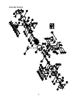
Page 18: ...18 Assembly Drawing...

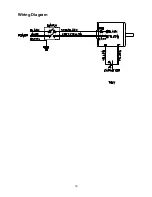
Page 19: ...19 Wiring Diagram...

Page 20: ...ll 1 800 274 6848 Monday through Friday 8 00 a m to 5 00 p m CST Having the Model Number and Serial Number of your machine available when you call will allow us to serve you quickly and accurately 427...

Reviews: