6
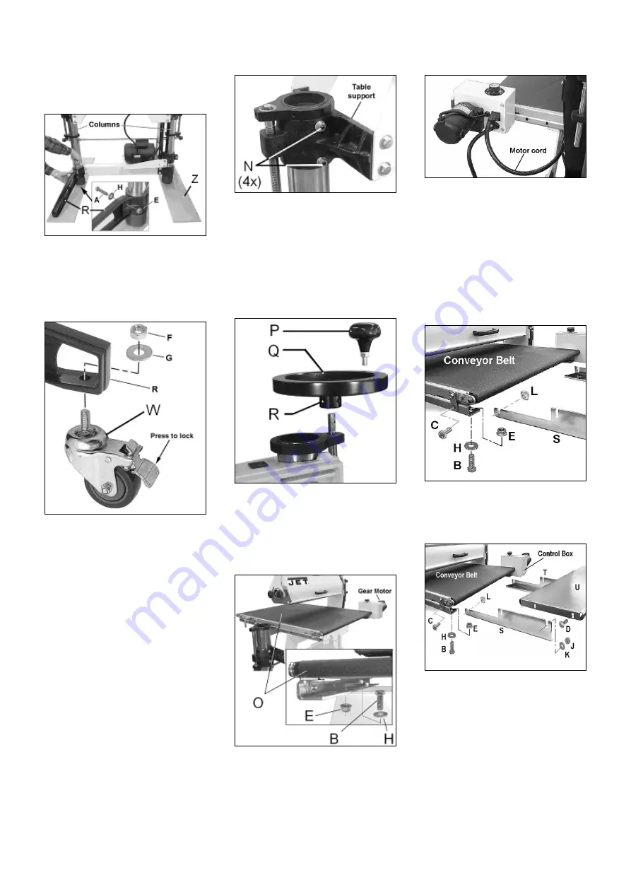
Use a forklift or hoist to rise the
machine and place it onto the
assembly fixtures (Z, Fig 6)
Fig 6
Mount the 4 legs (R) to the columns.
Lift the brush sander and remove the
assembly fixtures.
Mount the 4 wheels (W, Fig 7)
Fig 7
Adjust table support screws
Attention:
The set screws have been tightened
for shipment.
All 4 set screws must be loosened and
re-adjusted before operating the
height adjusting mechanism.
Failure to follow may damage the
miter gears.
Loosen each hex nut, then loosen the
4 set screws (N, Fig 8)
Fig 8
Re-tighten the set screws until they
only lightly touch the column.
Install handwheel
Attach the handwheel and tighten the
two set screws (R, Fig 9) with the
4mm hex wrench supplied
Fig 9
Conveyor Table Installation
Place the conveyor table (O, Fig 10)
onto the mounting brackets.
Secure the conveyor in place with four
hex head bolts, washers and nuts.
Fig 10
Plug the sander's motor cord into the
receptacle of the control box (Fig 11).
Fig 11
Important: The conveyor belt has been
over-tensioned for the purpose of
shipping.
Before operation, adjust the belt
tension (see chapter 7.5).
Install table extensions
Remove the hex bolt from the rail (C,
Fig 9)
Fig 9
Slide the supports (S, T, Fig 10) into
the rails and attach with bolts and
nuts.
Fig 10
Note:
You have to remove the control box
bottom cover to mount the right
support (T).
Install the tables (U).
Align the extension tables with the
help of a straight edge or a straight
piece of wood (Fig 11).


