background image


8

Collection bags: 
  Bag material ..................................................................................................................................... polyethylene 
  Drum collection bag size (Dia. x L) ............................................................ 30-11/16 x 32-11/16 (780 x 830 mm) 
  Canister collection bag size (Dia. x L) ...................................................... 19-11/16 x 23-5/8 in. (500 x 600 mm) 
 
Main materials: 
  Frame ................................................................................................................................................ steel tubing 
  Body .................................................................................................................................................. 18 ga. steel 
  Paint finish ................................................................................................................................... powder coated 
 
Dimensions: 
  Footprint/base dimensions (L x W) ............................................................. 50-5/8 x 25-7/8 in. (1286 x 658 mm) 
  Overall dimensions, assembled (L x W x H) ..................... 25-7/8 x 50-5/8 x 72-1/4 in. (658 x 1286 x 1835 mm) 
  Overall dimensions, shipping carton (L x W x H) .................. 45 x 26-9/16 x 41-3/8 in. (1145 x 675 x 1050 mm) 
   
Weights:


  Net weight ..................................................................................................................................... 207 lb. (94 kg) 
  Shipping weight, approximate ..................................................................................................... 235 lb. (107 kg) 


The  specifications  in  this  manual  were  current  at  time  of  publication,  but  because  of  our  policy  of  continuous 
improvement, JET reserves the right to change specifications at any time and without prior notice, without incurring 
obligations. 


Summary of Contents for JCDC-2

Page 1: ...2 2 0 HP Mobile Cyclone Dust Collector Original GB Operating Instructions JPW Tool AG Tämperlistrasse 5 8117 Fällanden Switzerland Phone 41 44 806 47 48 Fax 41 44 806 47 58 www jettools com M 717520M 2016 04 ...

Page 2: ...6 42 EC Machinery Directive Maschinenrichtlinie Directive Machines 2014 30 EU electromagnetic compatibility elektromagnetische Verträglichkeit compatibilité électromagnétique designed in consideration of the standards und entspechend folgender zusätzlicher Normen entwickelt wurde et été développé dans le respect des normes complémentaires suivantes EN ISO 12100 2010 EN 60204 1 2006 AC 2010 EN 5501...

Page 3: ...ranty period shall be reduced in proportion to the excess use but to no less than three months Returning rejected goods requires the prior express consent of the Seller and is at the Buyer s risk and expense Further warranty details can be found in the General Terms and Conditions GTC The GTC can be viewed at www jettools com or can be sent by post upon request The Seller reserves the right to mak...

Page 4: ...out microscopic particles 10 Do not operate this machine while tired or under the influence of drugs alcohol or any medication 11 Make certain the switch is in the OFF position before connecting the machine to the power supply Turn off all controls before unplugging 12 Make certain the machine is properly grounded Connect to a properly grounded outlet only See Grounding instructions 13 Make all ma...

Page 5: ... dust lint hair and anything that may reduce air flow 32 Do not operate without hose connected to the inlet Place cap on unused inlet port Hazardous moving parts inside Unplug before removing or connecting inlet or inlet guard 33 Use recommended accessories improper accessories may be hazardous 34 Maintain tools with care Follow instructions for lubricating and changing accessories 35 Turn off mac...

Page 6: ...cations and series number Figure 4 Warns user of hazardous voltage and should be open up by trained personnel only Figure 5 Warns user of heated hot surface hazard Figure 6 Indicate the main electrical power supply wire s location and the label itself Figure 7 Motor Fan Rotation Direction Figure 8 Notice the operator do not put the foot on the base Figure 9 Grounding Notice ...

Page 7: ...cy 99 of 2 micron particles Air Flow Rate with filters installed 1271 CFM 2159 m hr Air Velocity 6456 FPM 32 8 m s Static pressure loss WC 4 in H2O 102 mmH2O Maximum static pressure loss WC 7 5 in H2O 191 mmH2O Impeller Impeller diameter 14 1 2 in 368 mm Impeller type radial fin Impeller material steel Canister filter Filter type cartridge and spunbond polyester Canister filter diameter 14 9 16 in...

Page 8: ...25 7 8 in 1286 x 658 mm Overall dimensions assembled L x W x H 25 7 8 x 50 5 8 x 72 1 4 in 658 x 1286 x 1835 mm Overall dimensions shipping carton L x W x H 45 x 26 9 16 x 41 3 8 in 1145 x 675 x 1050 mm Weights Net weight 207 lb 94 kg Shipping weight approximate 235 lb 107 kg The specifications in this manual were current at time of publication but because of our policy of continuous improvement J...

Page 9: ...1 Drum lid H 1 Inlet adaptor I 1 Hose J 2 Hose clamp 12 1 2in K 4 Casters for Base L 4 Casters for Drum M 2 Side cap N 1 Handle O 1 Canister collection bag P 1 Drum collection bag Q 2 Quick lever R 1 Bag frame S consists of 4 long supports 4 short supports and 2 hoops 1 Stand support T 1 Foam tape 490 mm U 2 Foam tape 970 mm V 1 Foam tape 1265 mm W 1 Gasket X 1 Remote controller with batteries not...

Page 10: ... HP1 See Figure 3 2 Install left and right stands D1 D2 to base C with flange head screws HP8 3 Install stand support T to stands with flange head screws HP4 Figure 3 4 Install four casters M into the threaded nuts beneath drum F See Figure 4 Figure 4 5 Lift main housing A using hoist with straps through lifting rings atop main housing If hoist is not available at least 2 persons must lift housing...

Page 11: ...tween left and right stands D1 D2 and secure with flange head screws HP2 See Figure 5 Figure 5 7 Install funnel B beneath main housing Secure with funnel clamp G See Figure 6 Tighten screw on funnel clamp securely Figure 6 8 Install side cover N on left and right stands See Figure 7 ...

Page 12: ... Figure 8 10 Place gasket X between canister filter and main housing Install canister filter onto main housing and tighten with flange head screws HP8 and nuts HP9 See Figure 9 Figure 9 11 Apply foam tape U around inlet port near edge See Figure 10 The foam tape should completely encircle the port ...

Page 13: ...n bag P to bottom of canister filter and secure with steel bag clamp X Figure 10 15 Apply foam tape V around funnel just above its bottom edge See Figure 11 The foam tape should completely encircle the funnel 16 Apply foam tape V around outside lip of drum opening The foam should completely encircle the lip Figure 11 17 Install hose J onto cone and drum lid and secure with two hose clamps K at top...

Page 14: ...uts HP10 HP11 Note The bends on long supports point inward as shown Figure 13 19 Place drum collection bag Q into drum with its top edge wrapped around top edge of drum Place bag frame S inside bag and press down all the way See Figure 14 20 Pull down both quick levers R Figure 12 then assemble drum lid H Figure 12 to quick levers Tighten long nut R1 Figure 12 onto each quick lever 21 Raise drum l...

Page 15: ...nt grounding conductor and grounding plug The plug must be inserted into an appropriate outlet that is properly installed and grounded in accordance with all local codes and ordinances Improper connection of the equipment grounding conductor can result in a risk of electric shock Check with a qualified electrician or service person if you are in doubt as to whether the outlet is properly grounded ...

Page 16: ...or 8 hours The dust collector will stop automatically at end of selected period For continuous operation no timer select infinity position Figure 16 6 2 1 Remote controller reset If the remote controller begins to function improperly it should be cleared and reset To clear the remote controller press and hold reset button C Figure 16 for 3 seconds until receiver beeps 3 times To reset the controll...

Page 17: ...age to the motor The relay will open the circuit shut off the dust collector if the motor is drawing excessive current during extended periods of operation If the overload is tripped allow the machine to cool down for several minutes Then press reset button D Figure 15 and restart the dust collector 7 2 Cleaning and bag inspection Clean canister filter frequently to keep the collector s performanc...

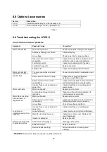
Page 18: ...Inspect all connections on motor for loose or shorted terminals or worn insulation Incorrect fuse or circuit breaker in power line Install correct fuse or circuit breaker at power source Motor overheats Motor overloaded Reduce load on motor Air circulation through motor is restricted Clean motor fan with compressed air to restore normal air circulation Motor stalls resulting in blown fuses or trip...

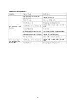
Page 19: ...led properly Inspect drum for leaks make sure lid is tight Canister filter is dirty Clean filter Wood has excess moisture content Use lumber with lower moisture content Obstruction in dust hose or inlet port Inspect and clear obstruction Dust hose too long Move collector closer to dust source Excess dust or large chips backing up into canister filter Collection drum not sealed properly Inspect dru...

Reviews: