background image


3

2.0

  Table of contents 

Section 


    Page 

1.0  Warranty and service ........................................................................................................................ 2


2.0  Table of contents .............................................................................................................................. 3


3.0  Safety warnings ................................................................................................................................ 4


4.0  About this manual ............................................................................................................................. 5


5.0  Specifications ................................................................................................................................... 6


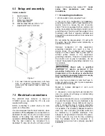
6.0  Setup and assembly ......................................................................................................................... 7


7.0  Electrical connections ....................................................................................................................... 7


7.1  Grounding instructions................................................................................................................... 7


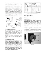
7.2  Voltage conversion ........................................................................................................................ 8


7.3  Extension cords ............................................................................................................................. 8


8.0  Operation.......................................................................................................................................... 8


8.1  Control switch ............................................................................................................................... 8


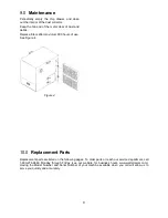
9.0  Maintenance ..................................................................................................................................... 9


10.0  Replacement Parts ......................................................................................................................... 9


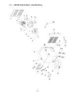
10.1.1  JDC-500 Dust Collector – Exploded View ............................................................................... 10


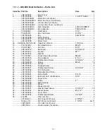
10.1.2  JDC-500 Dust Collector – Parts List ........................................................................................ 11


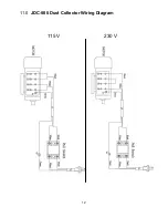
11.0  JDC-500 Dust Collector Wiring Diagram........................................................................................ 12


Summary of Contents for JDC-500

Page 1: ...anual Metal Dust Collector Model JDC 500 WALTER MEIER Manufacturing Inc 427 New Sanford Road LaVergne Tennessee 37086 Part No M 414700 Ph 800 274 6848 Revision A 12 2011 www waltermeier com Copyright 2011 Walter Meier Manufacturing Inc ...

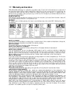
Page 2: ...stage prepaid to a location designated by us For the name of the location nearest you please call 1 800 274 6848 You must provide proof of initial purchase date and an explanation of the complaint must accompany the merchandise If our inspection discloses a defect we will repair or replace the product or refund the purchase price at our option We will return the repaired product or replacement at ...

Page 3: ...ns 6 6 0 Setup and assembly 7 7 0 Electrical connections 7 7 1 Grounding instructions 7 7 2 Voltage conversion 8 7 3 Extension cords 8 8 0 Operation 8 8 1 Control switch 8 9 0 Maintenance 9 10 0 Replacement Parts 9 10 1 1 JDC 500 Dust Collector Exploded View 10 10 1 2 JDC 500 Dust Collector Parts List 11 11 0 JDC 500 Dust Collector Wiring Diagram 12 ...

Page 4: ... in place at all times when the machine is in use If removed for maintenance purposes use extreme caution and replace the guards immediately after completion of maintenance 13 Check damaged parts Before further use of the machine a guard or other part that is damaged should be carefully checked to determine that it will operate properly and perform its intended function Check for alignment of movi...

Page 5: ...tions are not heeded it may result in serious injury or possibly even death 4 0 About this manual This manual is provided by Walter Meier Manufacturing Inc covering the safe operation and maintenance procedures for a JET Model JDC 500 Metal Dust Collector This manual contains instructions on installation safety precautions general operating procedures maintenance instructions and parts breakdown Y...

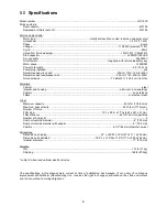
Page 6: ...on sparking Casters polyurethane Filters micro steel mesh Other Maximum capacity 490 cfm 13 88 cmm Maximum hose velocity 5610 fpm 1710 mpm Number of filters 2 Filter size 19 L x 9 5 w x 2 Thk 483 x 241 x 51 mm Filter efficiency 99 of 5 micron particles Number of dust ports 2 Dust port outside diameter 4 100 mm Dust port outside diameter with adaptor 3 76 2 mm Casters 2 1 2 64 mm diameter swivel Di...

Page 7: ...es Do not modify the plug provided if it will not fit the outlet have the proper outlet installed by a qualified electrician Improper connection of the equipment grounding conductor can result in a risk of electric shock The conductor with insulation having an outer surface that is green with or without yellow stripes is the equipment grounding conductor If repair or replacement of the electric co...

Page 8: ...extension cords is discouraged Try to place equipment within reach of the power source If an extension cord is necessary make sure it is in good condition and heavy enough to carry the current your product will draw An undersized cord will cause a drop in line voltage resulting in loss of power and overheating Table 1 shows correct size to use depending on cord length and nameplate ampere rating I...

Page 9: ...800 hours of use See Figure 4 Figure 4 10 0 Replacement Parts Replacement parts are listed on the following pages To order parts or reach our service department call 1 800 274 6848 Monday through Friday see our website for business hours www waltermeier com Having the Model Number and Serial Number of your machine available when you call will allow us to serve you quickly and accurately ...

Page 10: ...10 10 1 1 JDC 500 Dust Collector Exploded View ...

Page 11: ...1 13 JDC 500013 Impeller Ø11 1 14 JDC 500014 Washer 1 15 TS 1503051 Socket Head Cap Screw M6x20 1 16 JDC 500016 Hose Adaptor 4 to 3 2 17 JDC 500017 Phillips Head Screw 3 16 x3 8 2 18 JDC 500018 Screw M4x8 16 19 JDC 500019 Handle 2 20 JDC 500020 Tapping Screw 4 21 JDC 500021 Phillips Head Screw 3 16 x3 8 3 22 JDC 500022 Pull Out Switch 1 23 JDC 500023 Moveable Door Plate 1 24 JDC 500024 Strain Reli...

Page 12: ...12 11 0 JDC 500 Dust Collector Wiring Diagram 115 V 230 V ...

Reviews: