background image


15

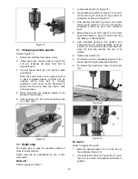
3.  Rotate lock ring (F) 

counterclockwise

 as far as 

it will turn. You should be able to feel and hear 
when the lock ring reaches the end of its 
rotation. 

4.  Tighten lock handle (G). 

5.  The bit will now stop at the marked depth 

when the downfeed handle is rotated. 

6.  To release the depth stop, loosen lock handle 

(G). 


Figure 22 


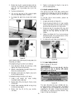
Figure 23 

NOTE: Method #2 allows rapid, fine adjustment to 
the setting, as follows: 

If the depth setting is found to be 

too shallow

1.  Hold downfeed handle (D) stationary while 

slightly loosening lock handle (G). 

2.  Slightly rotate downfeed handle to lower bit to 

the more accurate position. 

3.  Retighten lock handle (G). Depth is now set to 

more accurate position. 

If the depth setting is found to be 

too deep

1. Loosen lock handle (G) while holding 

downfeed handle stationary. 

2.  Slightly back off the lock ring (F), that is, rotate 

it 

clockwise

3.  Slightly rotate downfeed handle to bring bit up 

to more accurate depth. 

4.  Rotate lock ring (F) all the way 

counter-

clockwise.


5.  Tighten lock handle (G). Depth is now set to 

more accurate position. 

8.9

  Quill retraction lock 

The quill can be held in the down position and 
prevented from retracting, such as for operating a 
sanding drum or to facilitate removal of chuck and 
arbor. 

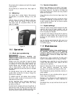
To lock the quill in down position, proceed as 
follows (Figure 24): 

1.  Loosen lock handle (G, Figure 24). 

2.  Rotate downfeed handle (D) to lower spindle 

to the point at which it is to be locked, and hold 
downfeed handle stationary in this position. 

3.  Rotate lock ring (F) 

clockwise

 all the way until 

it stops. You should be able to feel and hear 
when the lock ring reaches the end of its 
rotation. 

4.  Tighten lock handle (G). You can now release 

downfeed handle. The quill will remain in this 
lowered position until released. 

5.  To release the quill, loosen lock handle (G). 


Figure 24 

8.10

  Laser adjustment 

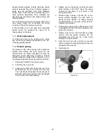
Refer to Figures 25, 26 and 27. 


Do not look directly into the 

laser beam or view it directly with optical 
instruments. See Figure 25.


Figure 25 

The Laser Assembly has been installed and pre-
set at the factory. It should, however, be checked 
for alignment and any adjustments made before 
operating the drill press. It should be re-checked 
periodically, as long-term machine vibration may 
cause it to become misaligned. 

Summary of Contents for JDP-17

Page 1: ...tions and Parts Manual 16 speed Woodworking Drill Press Model JDP 17 JET 427 New Sanford Road Part No M 716300 LaVergne Tennessee 37086 Revision B 05 2015 Ph 800 274 6848 ECR CN0069 www jettools com C...

Page 2: ...as Authorized Service Centers located throughout the United States For the name of an Authorized Service Center in your area call 1 800 274 6846 or use the Service Center Locator on the JET website Mo...

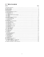
Page 3: ...ts 12 8 2 Table movement 12 8 3 Table insert leveling 13 8 4 Table slots 13 8 5 Chuck and arbor removal 13 8 6 Installing bits 13 8 7 Changing spindle speeds 14 8 8 Depth stop 14 8 9 Quill retraction...

Page 4: ...his machine while tired or under the influence of drugs alcohol or any medication 11 Make certain the switch is in the OFF position before connecting the machine to the power supply 12 Make certain th...

Page 5: ...eded it may result in serious or possibly even fatal injury 4 0 About this manual This manual is provided by JET covering the safe operation and maintenance procedures for a JET Model JDP 17 Drill Pre...

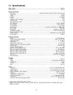
Page 6: ...on of handle 5 127 mm Quill diameter 2 05 52 mm Number of spindle speeds 16 Maximum no load speed range 210 to 3500 RPM Maximum spindle to table distance 29 740 mm Maximum spindle to base distance 46...

Page 7: ...65 H 724 x 483 x 1650 mm Shipping dimensions 56 L x 23 1 2 W x 11 1 2 H 1422 x 597 x 292 mm Net weight approximate 187 lb 85kg Shipping weight approximate 198 lb 90kg L length W width H height 5 1 Ba...

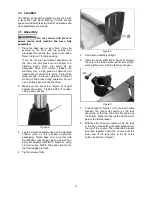
Page 8: ...urfaces After assembly exposed metal surfaces on the drill press should be periodically coated with a light application of paste wax or other rust protectant 6 2 Shipping contents Refer to Figures 2 a...

Page 9: ...Figure 4 is tight against the column Tighten further if needed using a 5mm hex key Figure 4 3 Lay the column assembly down on an elevated surface such as the included polystyrene packaging Attach bas...

Page 10: ...the bolt N into the table bracket hole then reinstall handle M spring and screw L Note The locking handle HP3 is adjustable To reposition pull out on the handle and rotate it then release it making su...

Page 11: ...is rated at 115V power and comes with a plug designed for use on a circuit with a grounded outlet that looks like the one pictured in A Figure 13 Before connecting to power source be sure the switch i...

Page 12: ...d nameplate ampere rating If in doubt use the next heavier gauge The smaller the gauge number the heavier the cord Ampere Rating Volts Total length of cord in feet More Than Not More Than 120 25 50 10...

Page 13: ...uill assembly with the downfeed handles to expose slot and lock it in the lowered position see sect 8 5 Quill retraction lock While maintaining the lowered quill position rotate spindle by hand to ali...

Page 14: ...nd 21 1 Loosen lock handle G Figure 21 2 Use downfeed handles D Figure 21 to lower the bit until it just contacts the top surface of workpiece as shown in Figure 20 3 Hold downfeed handle in position...

Page 15: ...set to more accurate position 8 9 Quill retraction lock The quill can be held in the down position and prevented from retracting such as for operating a sanding drum or to facilitate removal of chuck...

Page 16: ...orstner bits or sanding drums Figure 26 Figure 27 8 11 LED work light Refer to Figure 28 The integrated LED work light is adjustable for optimal angle to the table Push on the rim of the light to adju...

Page 17: ...handles set screws bolts etc are tight on the table and head Confirm that the drill bit is securely inserted inside the chuck jaws Clear all items such as tools and rags away from machine Before attem...

Page 18: ...etraction weaken after long term use of the drill press tighten the spring tension as follows 1 Disconnect machine from power source 2 Pull off cap A Figure 31 3 Loosen jam nut B and loosen inner nut...

Page 19: ...19 12 0 Speed chart Table 2 JDP 17 recommended drill speeds chart also located in machine hood...

Page 20: ...dle Lubricate spindle Loose pulleys or belts Make any needed corrections Verify that belts are properly tensioned Noisy motor Check motor bearings or for loose motor fan Wood splinters on underside of...

Page 21: ...21 14 1 1 JDP 17 Drill Press Exploded View...

Page 22: ...1 24 JDP17 024 Worm Shaft 1 25 JDP17 025 Pan Head Rivet 4 204 JDP17 204 Coil Spring Assembly 26 and 27 1 26 JDP17 026 Spring Housing 1 27 JDP17 027 Coil Spring 1 28 JDP17 028 Support 1 29 JDP17 029 Sp...

Page 23: ...ut 1 76 JDP17 076 Spindle Pulley 1 77 JDP17 077 Retaining Ring R52mm 2 209 JDP17 209 Drive Sleeve Assembly 78 thru 80 1 78 JDP17 078 Drive Sleeve 1 79 BB 6205VV Ball Bearing 6205 W 2 Seals 2 80 JDP17...

Page 24: ...o 92x38mm 1 123 JDP17 123 Warning Label Laser 1 124 JDP17 124 Motor Label 1 125 JDP17 125 Warning Label 1 212 JDP17 212 Table Wrench Assembly 126 135 136 1 126 JDP17 126 Wrench 1 127 TS 1550061 Flat W...

Page 25: ...25 15 0 Electrical Connections JDP 17 Drill Press 1 Phase 115V only...

Page 26: ...26 This page intentionally left blank...

Page 27: ...27 This page intentionally left blank...

Page 28: ...28 427 New Sanford Road LaVergne Tennessee 37086 Phone 800 274 6848 www jettools com...

Reviews: