13
fence until the angle of the fence matches
the bevel of your gauge piece.
5. Tighten locking handle (C, Fig 8-2).
4.
Important:
When the tilted operation is
finished and the fence is returned to 90°, do
not forget to flip the 90° stop block (D, Fig.
8-2) back to its original position.
To tilt fence backward
5. The fence can be tilted backward up to 45°
(that is, for a total included angle of 135°
from table surface).
6. Loosen locking handle (C, Fig. 8-2).
7. Flip the 90° stop block (D, Fig. 8-2) out of
the way.
8. Move the lever (B, Fig. 8-2) back to the
desired angle up to 135 degrees. Or you can
place
8.3
Fence stop adjustments
Periodically check the 90° and 45° backward
(135°) tilt accuracy of the fence with an angle
measuring device, such as an adjustable square
or machinist’s protractor.
90º Fence adjustment
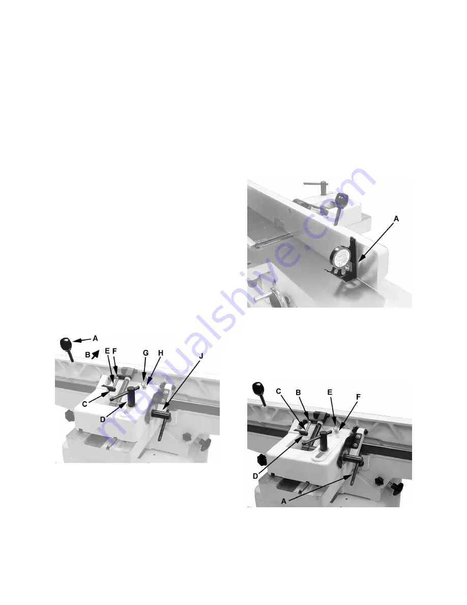
Refer to Figure 8-3:
The 90º stop is controlled by the
stop bolt
(E)
and the
stop plate
(C).
Figure 8-3
1. Set the infeed table to approximately the
same height as the outfeed table.
2. Move the fence by releasing
lock handle
(D)
and pushing the fence assembly until it
overlaps the tables (B).
3. Tighten
lock handle
(D).
4. Adjust the fence to a 90º angle by releasing
lock handle
(J), pulling up on the
fence
handle
(A), and tightening the
lock handle
(J).
Note:
The
stop bolt
(E) should be resting
against the
stop plate
(C).
5. Place an angle measuring device on the
table and against the fence to confirm a 90º
setting (A, Fig. 84).
6. If the fence is not square to the table,
release the
lock handle
(J), loosen the hex
nut (F), and turn the
stop bolt
(E) until the
fence is square to the table.
7. Tighten the lock nut (F) to retain the setting.
Tighten the lock handle (J).
Figure 8-4
45º Fence backward stop adjustment
Refer to Figure 8-5:
The 45º fence backward stop (fence positioned
away from the operator) is controlled by the
stop
bolt
(E).
Figure 8-5
1. Loosen the lock handle (A). Move the stop
plate (D) out of the way and position the
fence at the 135º angle. Make sure the
fence sits against the stop bolt. (E).
Summary of Contents for JJ-6HHDX
Page 27: ...27 15 1 1 Fence Assembly All Models Exploded View...
Page 29: ...29 15 2 1 Stand Assembly JJ 6CSDX Exploded View...
Page 31: ...31 15 3 1 Stand Assembly JJ 6HHDX only Exploded View...
Page 33: ...33 15 4 1 Bed Assembly All models Exploded View...
Page 37: ...37 16 0 Wiring diagrams All Models...
Page 39: ...39 This page intentionally left blank...
Page 40: ...40 427 New Sanford Road LaVergne Tennessee 37086 Phone 800 274 6848 www jettools com...


