5
Dispose of the packing in an
environmentally friendly manner.
Clean all rust protected surfaces with
a mild solvent.
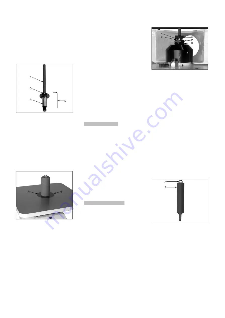
Thoroughly clean the arbors ( A, Fig
1) on all of the spindle assemblies.
Also clean the arbor housing on the
sander.
Fig 1
Slip the sanding sleeves (B) over the
spindle and hold in place by tightening
the screw (C) with the supplied 2mm
hex wrench (D)
Install the sanding spindle to the
sander (see chapter 7.1)
Install the table insert (A, Fig2) which
most closest fits the sanding sleeve.
Line up the notch in the insert with the
pin in the table (B)
Fig 2
5.3 Mains connection
Mains connection and any extension
cords used must comply with
applicable regulations.
The mains voltage must comply with
the information on the machine
licence plate.
The mains connection must have a
10 A surge-proof fuse.
Only use power cords marked
H07RN-F
Connections and repairs to the
electrical equipment may only be
carried out by qualified electricians.
5.4 Dust connection
Before initial operation, the machine
must be connected to a dust collector.
The suction should switch on
automatically when the sander is
switched on.
The flow rate on the 100mm suction
port must be 20m/sec.
Flexible hoses must be of non-
flammable quality, and must be
connected to the dust collector ground
system.
5.5 Starting operation
You can start the machine with the
green on button. The red button on the
main switch stops the machine.
6. Machine operation
Feed the workpiece straight across the
machine table, holding your fingers
close together, guiding the workpiece
with the palm of your hands.
Don’t put your hands under the
machine table.
Always keep your hands well clear of
the rotating sanding drum.
When working complex shapes, make
jigs and guides to guide the workpiece
properly and safely.
Support long workpieces with helping
roller stands.
For bevel sanding the table can be
tilted
7. Setup and adjustments
General note:
Setup and adjustment work may
only be carried out after the
machine is protected against
accidental starting by pulling the
mains plug.
7.1 Installing spindles
Disconnect the machine from the
power source.
Before inserting the threaded spindle
(A, Fig 3) into the spindle holder (B)
make sure the surfaces are clean.
Fig 3
Using the provided wrenches, tighten
the arbor nut (D) colckwise while
holding the lower arbor housing nut
(C) with the other wrench.
Do not over tighten the spindle as it
may be difficult to remove.
Removing Sanding spindles:
Disconnect the machine from the
power source.
Use the provided wrenches to hold the
upper arbor housing nut (E, Fig 3)
while turning the arbor nut (D) counter
clockwise.
7.2 Changing sanding sleeves
Disconnect the machine from the
power source.
On the 6, 9, 12, 16mm spindles
loosen the sleeve clamp screw
(C, Fig 1).
On the 19, 25, 38, 50, 75 and 100mm
spindles loosen the nut (A, Fig 4).
Fig 4
Remove the sanding sleeve from the
spindle shaft or drum.
Reverse these steps to install the new
sanding sleeve.
7.3 Setup for 90°
Disconnect the machine from the
power source.
Use a square (E, Fig 5) on the
sanding drum to exactly align the
table to 90°.


