background image


12

The scale (E) indicates the selected thickness. 

Retighten the table clamping handle. 

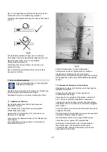
Correct operating position: 

To feed the workpiece into the machine, position yourselves 
offset to one side of the feed opening. 


Workpiece handling: 

Adjust the planer table to the workpiece thickness. 


Fig17 

Feed workpiece slowly and straight into the thicknesser. 
It will then be automatically fed through the thicknesser. 
Guide workpiece straight through the thicknesser. 
To remove the workpiece from the machine, position 
yourselves offset to one side of the outfeed opening. 

Support long workpieces with helping roller stands. 


Operating notes: 

Always use sharp cutter knives! 

Feed with thicker workpiece end at the front, hollow side 
downward. 

Max. 2mm depth of cut. 
If a workpiece gets stuck lower the table by app. ½ crank 
turn. 

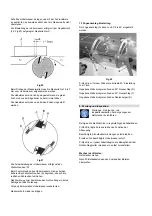
Plane the stock with the grain, if possible (Fig 18). 


Fig 18 

You get a better surface when planing several passes with 
less chip removal. 

Switch machine off if no further planning is to be done 
immediately afterwards. 

Workpieces shorter than 160 mm may not be processed. 

Machine max. 2 workpieces at one time. Feed on both outer 
sides. 


7.  Setup and adjustments 

Setup and adjustmenst may only be performed  
when the mains plug is pulled! 


Cutter knives are extremely sharp! Use caution when 
handling. Risk of personal injury by cuts. 

Failure to comply may cause serious injury. 


7.1 Knife removal: 

Disconnect machine from power source. 

Wear suitable gloves when changing cutter knives. 

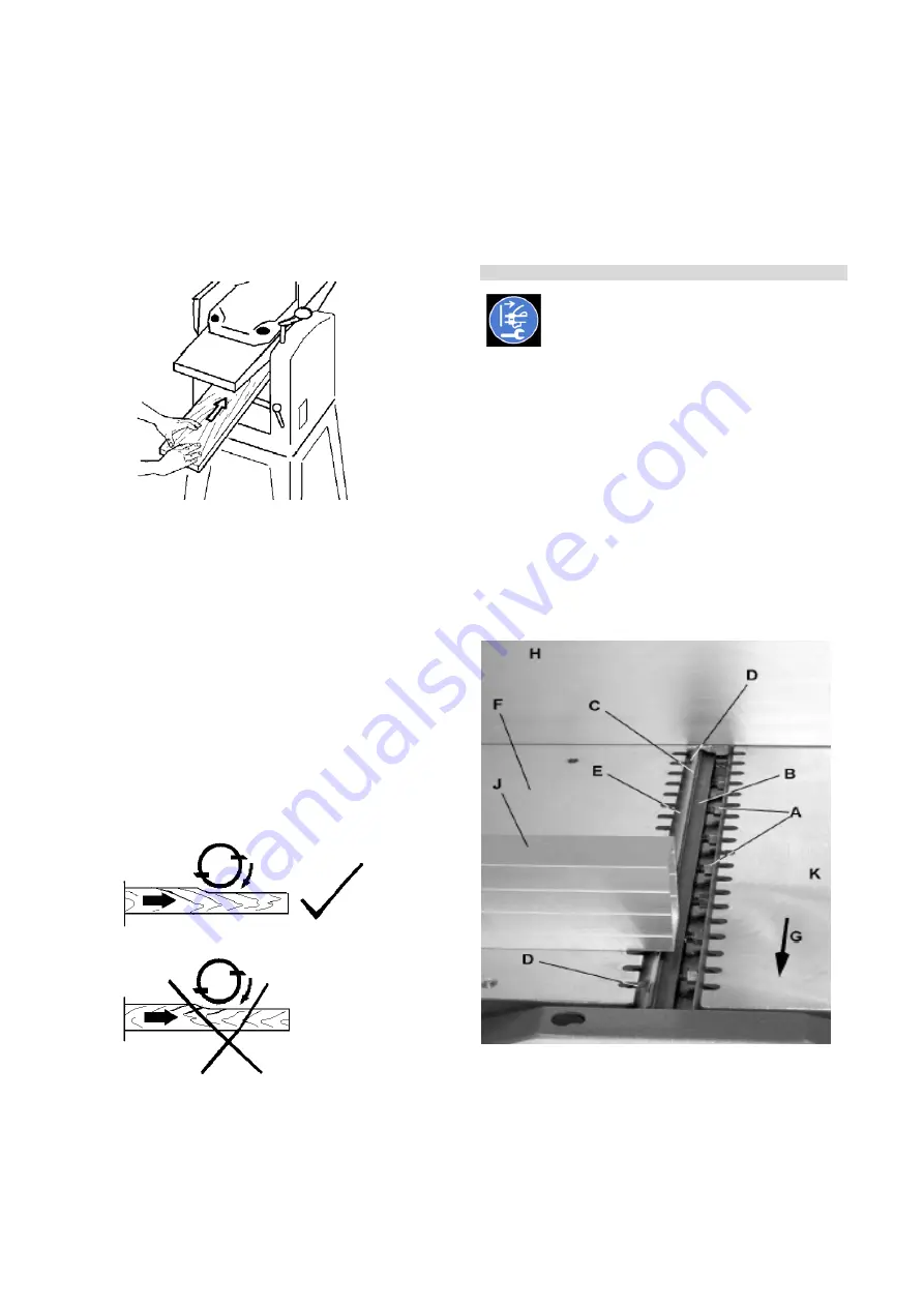
Slide cutter guard (C) away from fence (A), which will 
expose the cutterhead. 

Loosen the hex-head bolts (A) of the knife lock bar by 
turning in a clockwise direction as viewed from the infeed 
table (K). Wear gloves ! 


Fig 19 

At first remove cutter knife (C), then knife lock bar (B) from 
the cutter block (E). 

Clean all surfaces of cutter block and cutter knife lock bar 
with a suitable solvent (do not use cleaning agents that 
could corrode the light metal components). 

Summary of Contents for JPT-8B-M

Page 1: ...T 10B M PLANER THICKNESSER Original GB Operating Instructions Translations D Gebrauchsanleitung F Mode d emploi TOOL FRANCE SARL 9 Rue des Pyr n es 91090 LISSES France www jettools com M 707410M 70740...

Page 2: ...Maschinenrichtlinie Directive Machines 2014 30 EU electromagnetic compatibility elektromagnetische Vertr glichkeit compatibilit lectromagn tique 2011 65 EU RoHS directive RoHS Richtlinie Directive Ro...

Page 3: ...essness accidental damage repair inadequate maintenance or cleaning and normal wear and tear Any warranty details i e warranty period can be found in the General Terms and Conditions GTC that are inte...

Page 4: ...medication can change your behaviour Never reach into the machine while it is operating or running down Never leave a running machine unattended Before you leave the workplace switch off the machine K...

Page 5: ...protection Use a suitable dust exhaust system The use of incorrect mains supply or a damaged power cord can lead to injuries caused by electricity 4 Machine specifications 4 1 Technical data JPT 8B M...

Page 6: ...er to make a better estimation of the hazards and risks involved 4 3 Content of delivery Jointer Planer F Jointer fence A Cutter head guard C Planer outfeed enxtension J Dust chute B Hose adapter 57 1...

Page 7: ...ort and start up 5 1 Transport and installation The machine is designed to operate in closed rooms and must be placed stable on firm and levelled ground The machine can be bolted down if required Wrap...

Page 8: ...o hex nuts Mounting jointer planer to stand Fig 4 Place the Jointer Planer F onto the assembled stand and attach with 4 socket head cap screws BB lock washers KK and flat washers JJ Tighten screws wit...

Page 9: ...marked H05VV F Connections and repairs to the electrical equipment may only be carried out by qualified electricians 5 4 Dust connection Before initial operation the machine must be connected to a du...

Page 10: ...the work piece with the palm of your hands Never put your hands under the cutter block cover Always keep your hands well clear of the cutter block Do not pull the work piece back over the unguarded c...

Page 11: ...and planing of short workpieces may only be performed with the help of tailor made push woods and templates 6 2 Thicknessing Disconnect machine from power source before making any adjustments Failure...

Page 12: ...You get a better surface when planing several passes with less chip removal Switch machine off if no further planning is to be done immediately afterwards Workpieces shorter than 160 mm may not be pr...

Page 13: ...rotrudes over the edge of the cutter block Adjust the knives according to the knife setting gauge J resting on the outfeed table F2 Fig 20 When turning the cutter block the adjustment gauge must move...

Page 14: ...protective and safety devices must be re attached immediately after completed cleaning repair and maintenance work Repair and maintenance work on the electrical system may only be carried out by a qu...

Page 15: ...ental protection Protect the environment Your appliance contains valuable materials which can be recovered or recycled Please leave it at a specialized institution This symbol indicates separate colle...

Page 16: ...Garantie TOOL FRANCE SARL garantiert dass das die von ihr gelieferte n Produkt e frei von Material und Herstellungsfehlern ist Diese Garantie deckt keinerlei M ngel Sch den und Fehler ab die direkt od...

Page 17: ...nen und zum F hren der Werkst cke gegeben ist Sorgen Sie f r gute Beleuchtung Die Maschine ist zum Gebrauch in geschlossenen R umen achten Sie darauf dass die Maschine standsicher auf festem und ebene...

Page 18: ...zugleich Um nicht parallele Fl chen zu dickenhobeln geeignete Zuf hrhilfen verwenden passende Zuf hrladen herstellen Nicht auf der Maschine stehen Arbeiten an der elektrischen Ausr stung der Maschine...

Page 19: ...enholz 100mm Schalleistungspegel nach EN ISO 3746 Leerlauf LwA 101 5 dB A Bearbeitung LwA 105 8 dB A Schalldruckpegel nach EN ISO 11202 Leerlauf LpA 88 7 dB A Bearbeitung LpA 96 4 dB A Die angegebenen...

Page 20: ...4 4 Maschinenbeschreibung Fig 1 A Abgabetisch B F geanschlag C Dicken Kurbel D Messerschutz E Aufgabetisch F Dickentisch Verl ngerung G berlastschutz H EIN AUS Schalter I Dickentisch Klemmung J Absau...

Page 21: ...Betrieb Entsorgen Sie die Verpackung erst wenn die Maschine montiert ist und zu Ihrer Zufriedenheit l uft Entsorgen Sie die Verpackung bitte umweltgerecht Entfernen Sie das Rostschutzfett mit einem m...

Page 22: ...erl ngerung etwas h her als den Dickentisch F4 einstellen Zum Anheben des Tisches die Gewindestifte im Uhrzeigersinn drehen Ein 4mm Inbusschl ssel ist mitgeliefert Dickentisch Klemmung Fig 6 Montieren...

Page 23: ...ieren Sie den Absauganschluss B im Dickentisch Einzugsbereich Die 2 Positionsnoppen und das Montagegewinde m ssen mit den Bohrungen im Dickentisch F1 bereinstimmen Kurbeln Sie den Dickentisch nach obe...

Page 24: ...e Werkst ck an den Werkst ckanschlag anlegen Die H he des Messerschutzes an das Werkst ck anpassen Beim F hren des Werkst cks gleiten die H nde ber den Messerschutz hinweg Fig 11 Fig 11 Hobeln von Sch...

Page 25: ...n und F gen Fig 15 Schieben Sie den Messerschutz C zur Seite damit wird die Hobelwelle frei Achtung Hobelmesser sind gef hrlich scharf Seien Sie vorsichtig im Hobelwellenbereich Hohes Verletzungsrisik...

Page 26: ...elmesser Andr ckleiste Vom Aufgabetisch K aus gesehen im Uhrzeigersinn Handschuhe benutzen Fig 19 Zun chst Hobelmesser C dann Hobelmesser Andr ckleiste B aus der Messerwelle E entfernen Oberfl chen de...

Page 27: ...eine Schl ge auf das Werkzeug Vorgang beim zweiten Hobelmesser wiederholen Messerschutz wieder anbringen 7 3 F geanschlag Einstellung Der F geanschlag A kann von 90 bis 45 eingestellt werden Fig 22 Pr...

Page 28: ...rlastschutzschalter dr cken und neu starten Starke Maschinenvibrationen Maschine steht uneben Ausgleich schaffen Hobelmesser unterschiedlich Messerbreite muss gleich sein Besch digtes Hobelmesser Mess...

Page 29: ...ie es nur an einer spezialisierten Entsorgungsstelle Dieses Symbol verweist auf die getrennte Sammlung von Elektro und Elektronikger ten gem Forderung der WEEE Richtlinie 2012 19 EU Diese Richtlinie i...

Page 30: ...produit satisfait aux normes conform ment aux lignes directrices indiqu es page 2 2 Garantie JPW Tool AG garantit que le les produit s fourni s est sont exempt s de d fauts mat riels et de d fauts de...

Page 31: ...stable et plat S assurer que le c ble d alimentation ne g ne pas le travail ni ne risque de faire tr bucher l op rateur Conserver le sol autour de la machine propre sans d chets huile ou graisse Pr t...

Page 32: ...espectant les directives et les consignes de s curit les risques suivants existent Contact avec l arbre dans la zone coupe Pour une protection efficace toujours adapter la protection des lames la dime...

Page 33: ...iveaux de bruit et ne sont pas forc ment les niveaux pour un travail s r Bien qu il existe un rapport entre les niveaux d mission et la nuisance nous ne pouvons pas savoir si des pr cautions suppl men...

Page 34: ...e Fig 1 A Table de d gagement B Guide de rainure C Manivelle d paisseur D Prot ge lame E Table de distribution F Rallonge de table de rabotage G Coupe circuit H Commutateur marche arr t I Blocage de l...

Page 35: ...e jeter l emballage que lorsque la machine est mont e et qu elle fonctionne correctement Eliminer l emballage dans le respect de l environnement Enlever la protection antirouille avec un dissolvant Mo...

Page 36: ...rement plus haut que la table de rabotage F4 Pour relever la table tourner les vis sans t te dans le sens des aiguilles d une montre Une cl pour vis six pans creux de 4 mm est jointe la livraison Fix...

Page 37: ...aspiration B dans la zone d attraction de la table de raboteuse Les 2 marques de positionnement et le filetage de montage doivent correspondre avec les trous de la table de rabotage F1 Relever la tabl...

Page 38: ...de pi ces de hauteur jusqu 75mm Poser la pi ce contre le guide Ajuster la hauteur du prot ge lame la pi ce En menant la pi ce les mains glissent au dessus du prot ge lame Fig 11 Fig 11 Rabotage d une...

Page 39: ...ot ge lame sur le c t C ainsi l arbre de rabot est d gag Attention Les fers de rabotage sont tr s ac r s Il faut tre tr s prudent dans la zone de l arbre du rabot Grand danger de blessures Positionner...

Page 40: ...d une montre Porter des gants Fig 19 Retirer de l arbre E tout d abord le fer C ensuite la barre de contre pression du fer B Nettoyer les surfaces de l arbre et de la barre de contre pression avec un...

Page 41: ...ifier l angle correct 90 par rapport la table Le cas chant corriger l angle 90 de la but e fixe D Le cas chant corriger l angle 45 de la but e fixe F Le cas chant corriger la graduation B 8 Entretien...

Page 42: ...diff rentes Largeur des lames doit tre identique Lame endommag e Remplacer la s rie de lames Surface travaill e pas nette Lame us e Remplacer par des lames coupantes Trop de copeaux sur la lame Enlev...

Page 43: ...e sp cialis de recyclage Ce symbole indique une collecte s par e des quipements lectriques et lectroniques conform ment la directive DEEE 2012 19 UE Cette directive n est efficace que dans l Union eur...

Reviews: