background image


The specified values are emission 
levels and are not necessarily to be 
seen as safe operating levels. 
As workplace conditions vary, this 
information is intended to allow the user 
to make a better estimation of the 
hazards and risks involved only. 


4.3 Content of delivery 

Base assembly with motor 
Sanding belt 60 grit 
Sanding disc 60 grit 
2 tables 
Mitre gauge 
Operating tools 
Assembly kit 
Operating manual 
Spare parts list. 


5.  Transport and start up 
 
5.1 Transport and installation 

For transport use a forklift or hand 
trolley. Make sure the machine does 
not tip or fall off during transport. 

The machine is designed to operate in 
closed rooms and must be placed 
stable on firm and levelled ground. 
The machine can be bolted down if 
required. 

For packing reasons the machine is 
not completely assembled. 


5.2 Assembly 

If you notice any transport damage 
while unpacking, notify your supplier 
immediately. Do not operate the 
machine! 

Dispose of the packing in an 
environmentally friendly manner. 

Clean all rust protected surfaces with a 
mild solvent. 

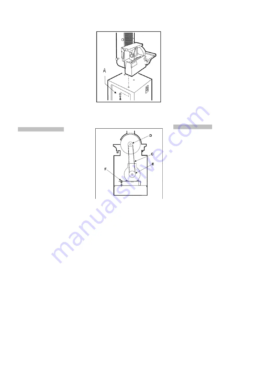
Mount the sander to the machine stand 
and connect with 4 lock bolts, washers 
and spring washers 
(A, Fig 1). 


Fig 1 

Install the drive belt (C, Fig 2). 

Adjust the belt tension by adjusting the 
nuts (F, Fig 2). 


Fig 2 


Close and lock the cabinet door. 


5.3 Mains connection 

Mains connection and any extension 
cords used must comply with 
applicable regulations. 
The mains voltage must comply with 
the information on the machine licence 
plate.  

The mains connection must have a 
16A surge-proof fuse. 

Only use power cords marked H07RN-

Connections and repairs to the 
electrical equipment may only be 
carried out by qualified electricians.  


5.4 Dust connection 

Before initial operation, the machine 
must be connected to a dust collector. 
The suction should switch on 
automatically when the belt sander is 
switched on. 
The flow rate on the 100mm suction 
port must be 20m/sec. 
Flexible hoses must be of non-
flammable quality, and must be 
connected to the dust collector ground 
system. 


5.5 Starting operation 

You can start the machine with the 
green on button. The red button on the 
main switch stops the machine. 


6.  Machine operation 

Feed the workpiece straight across the 
machine table, holding your fingers 
close together, guiding the workpiece 
with the palm of your hands. 

Don’t put your hands under the 
machine table. 

Always keep your hands well clear of 
the moving sanding belt or disc. 

When working complex shapes, make 
jigs and guides to guide the workpiece 
properly and safely . 

Support long workpieces with helping 
roller stands. 

For bevel sanding the tables can be 
tilted. Adjust the tables to keep a 
distance between the sanding paper 
and the table edge of 2 mm. 


6.1 Vertical belt sanding: 

When sanding in the vertical position, 
the table attachment must be 
positioned as sanding table (Fig 3). 

The table can be tilted at any angle 
between 90° and 45°  

Summary of Contents for JSG-31A

Page 1: ...t Sander Original GB Operating Instructions Translations D Gebrauchsanleitung F Mode d emploi JPW Tool AG Tämperlistrasse 5 CH 8117 Fällanden Switzerland Phone 41 44 806 47 48 Fax 41 44 806 47 58 www jettools com M JSG 31A 2017 03 ...

Page 2: ...correspond aux directives suivantes 2006 42 EC Machinery Directive Maschinenrichtlinie Directive Machines 2014 30 EU electromagnetic compatibility elektromagnetische Verträglichkeit compatibilité électromagnétique designed in consideration of the standards und entspechend folgender zusätzlicher Normen entwickelt wurde et été développé dans le respect des normes complémentaires suivantes EN ISO 121...

Page 3: ... These GTC can be viewed at the website of your dealer or sent to you upon request JPW Tool AG reserves the right to make changes to the product and accessories at any time 3 Safety 3 1 Authorized use This disc belt sander is designed for sanding wood and similar materials only Sanding of other materials is not permitted and may be carried out in specific cases only after consulting with the manuf...

Page 4: ...remove any nails and other foreign bodies from the workpiece Make sure to guide and hold the workpiece thigh during machining Machine only stock which rests securely on the table Specifications regarding the maximum or minimum size of the workpiece must be observed Do not remove chips and workpiece parts until the machine is at a standstill Do not stand on the machine Connection and repair work on...

Page 5: ...on cords used must comply with applicable regulations The mains voltage must comply with the information on the machine licence plate The mains connection must have a 16A surge proof fuse Only use power cords marked H07RN F Connections and repairs to the electrical equipment may only be carried out by qualified electricians 5 4 Dust connection Before initial operation the machine must be connected...

Page 6: ... table may be adjusted at any angle from 15 up to 45 down An adjustable 45 stop C Fig 7 is located under the table Fig 7 An adjustable 0 stop F Fig 8 is located on the back of the machine and must be swung out of position for the table to be tilted down Fig 8 7 Setup and adjustments General note Setup and adjustment work may only be carried out after the machine is protected against accidental sta...

Page 7: ...he direction indicated on the belt cover Observe the belt position on the rollers Edge of belt should remain even with the edge of the rollers Release the tracking lock nut G Fig 14 The blade tracking is now adjustable by turning the micro adjusting screw F Fig 14 If the belt has a tendency to track left of centre turn the micro adjusting screw clockwise and vice versa Clamp the tracking lock nut ...

Page 8: ... even support Abrasive belt keeps tearing Belt is running the wrong direction observe arrow on the sanding belt Sanded edge not square Table not square to sanding disc Adjust positive stop for 90 Sanding marks on the wood Workpiece was held still keep workpiece moving Wrong grit sanding belt use coarser grit for stock removal and fine grit for finish sanding Feed pressure too high never force the ...

Page 9: ...en Verschleiß zurückzuführen sind Die ausführlichen Garantieleistungen z B Gewährleistungsfrist sind den Allgemeinen Geschäftsbedingungen AGB zu entnehmen Die AGB sind auf der Internetseite ihres Händlers einzusehen oder werden auf Anfrage per Post zugestellt JPT Tool AG behält sich das Recht vor jederzeit Änderungen am Produkt und Zubehör vorzunehmen 3 Sicherheit 3 1 Bestimmungsgemäße Verwendung ...

Page 10: ...en Sie die Maschine nicht in der Nähe von brennbaren Flüssigkeiten oder Gasen Beachten Sie die Brandmelde und Brandbekämpfungsmöglichkeiten z B Standort und Bedienung von Feuerlöschern Benützen Sie die Maschine nicht in feuchter Umgebung und setzen Sie sie nicht dem Regen aus Achten Sie stets darauf dass keine zu große Staubkonzentration entsteht verwenden Sie stets eine geeignete Absauganlage Hol...

Page 11: ...den Aus verpackungstechnischen Gründen ist die Maschine nicht komplett montiert 5 2 Montage Wenn Sie beim Auspacken einen Transportschaden feststellen benachrichtigen Sie umgehend Ihren Händler nehmen Sie das Gerät nicht in Betrieb Entsorgen Sie die Verpackung bitte umweltgerecht Entfernen Sie das Rostschutzfett mit einem milden Lösungsmittel Montieren Sie die Schleifmaschine auf dem Maschinenunte...

Page 12: ...scheinheit als Anschlag siehe Kapitel 7 2 Der Anschlag kann zwischen 90 und 45 eingestellt werden Der Längsanschlag A Fig 4 muss montiert werden um das Werkstück zu stoppen Fig 4 Für einen gezogenen Schrägschliff kann der Anschlag quer zum Schleifband eingestellt werden Fig 5 Fig 5 6 3 Kontur Bandschleifen Klappen Sie dazu die Bandrollenabdeckung nach hinten Fig 6 Fig 6 Achtung Die Bandrollenabdec...

Page 13: ...lung bringen Lösen Sie den Klemmgriff A Fig 14 und öffnen Sie die Rollenabdeckung B Fig 14 Entfernen Sie die Seitenabdeckung C Fig 15 Fig 15 Mittels Klemmgriff E Fig 14 die Bandspannung lösen Schleifband vorsichtig entnehmen Neues Schleifband auflegen dabei auf angegebene Bandlaufrichtung achten Schleifband spannen Die Schutzabdeckungen wieder schließen Hinweis Schleifbänder dehnen sich im Betrieb...

Page 14: ... und den Indexierbolzen B Fig 10 monatlich leicht ölen 9 Störungsabhilfe Motor startet nicht Kein Strom Netzsicherung prüfen Motor Schalter oder Kabel defekt Elektrofachkraft kontaktieren Schleifband rutscht durch Schleifband ist lose Schleifband nachspannen Anpressdruck zu kräftig Werkstück beim Arbeiten bewegen Schleifteller stoppt Motorriemen lose Riemen nachspannen Anpressdruck zu kräftig Werk...

Page 15: ...a maintenance ou le nettoyage incorrects et l usure normale Les détails sur la garantie période de garantie par exemple peuvent être trouvés dans les conditions générales GTC faisant partie intégrante du contrat Ces conditions générales peuvent être consultées sur le site web de votre revendeur ou vous être envoyées sur demande JPW Tool AG se réserve le droit d effectuer des changements sur le pro...

Page 16: ...r une production de poussières trop élevée La poussière de bois est explosive et peut être nocive pour la santé Les poussières de certains bois exotiques et de bois durs tel que le hêtre et le chêne sont classées comme étant cancérigènes Retirer les clous et autres corps étrangers de la pièce avant de débuter l usinage Bien tenir et guider toutes les pièces à usiner N usiner que des pièces qui se ...

Page 17: ... d entraînement C fig 2 Tendre la courroie en ajustant l écrou F fig 2 Fig 2 Fermer et sécuriser la porte du socle 5 3 Raccordement au réseau électr Le raccordement ainsi que les rallonges utilisées doivent correspondre au règlement Le voltage et la fréquence doivent être conforme aux données inscrites sur la machine Le fusible du secteur électrique doit avoir 16A N utiliser pour le raccordement q...

Page 18: ... 6 4 Ponçage par disque L angle de la table peut être positionné entre 15 vers le haut et 45 vers le bas La buttée réglée à 45 C fig7 se trouve sous la table Fig 7 La buttée réglée à 0 F fig 8 au bord arrière de la table doit être pivotée pour basculer Fig 8 7 Adaptations et Réglages Attention Faire tous les travaux d adaptation ou de réglage après avoir déconnecté la machine du réseau 7 1 Orienta...

Page 19: ...a bande G Fig 14 Corriger le circuit de la bande avec la vis de micro réglage F Fig 14 Si le circuit de bande a tendance à tirer sur la gauche tourner la vis de micro réglage dans le sens des aiguilles d une montre et vice versa Resserrer le blocage de circuit de bande Mettre plusieurs fois le moteur en marche par à coups et vérifier le circuit de la bande 7 5 Chang papier abrasif du disque Déconn...

Page 20: ... se déchire plusieurs fois Mauvais montage de la bande Vérifier le sens de la bande Equerre de ponçage pas 90 Angle de ponçage 90 mal réglé Ajuster la buttée Résultat de ponçage insuffisant Pièce à usiner est restée immobile Bouger la pièce en travaillant Grain de bande non adapté Grain gros pour rifler grain fin pour polir Trop de pression sur la pièce Ne jamais forcer le façonnage 10 Protection ...

Reviews: