3
2.0
Table of contents
Section
Page
1.0 Warranty and service ..................................................................................................................................... 2
2.0 Table of contents ............................................................................................................................................ 3
3.0 Safety warnings .............................................................................................................................................. 5
4.0 About this manual .......................................................................................................................................... 6
5.0 Specifications ................................................................................................................................................. 7
5.1 Machine dimensions – JTM-949EVS/230, JTM-1050EVS2 ....................................................................... 8
5.2 Overview and terminology – JTM-949EVS/230, JTM-1050EVS2 .............................................................. 9
6.0 Set-up and assembly ................................................................................................................................... 10
6.1 Contents of shipping container ................................................................................................................. 10
6.2 Preparing the mill for service .................................................................................................................... 10
7.0 Electrical connections .................................................................................................................................. 11
7.1 General electrical cautions ....................................................................................................................... 11
7.2 Wire sizes ................................................................................................................................................. 11
8.0 Lubrication .................................................................................................................................................... 12
9.0 Operating instructions .................................................................................................................................. 12
9.1 Operating controls .................................................................................................................................... 12
9.2 Control panel ............................................................................................................................................ 12
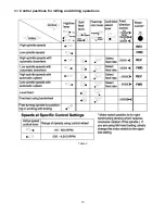
9.3 Control positions for milling and drilling operations .................................................................................. 13
9.4 Electronic variable speed ......................................................................................................................... 14
9.5 Spindle brake ........................................................................................................................................... 14
9.6 High-neutral-low shift lever ....................................................................................................................... 14
9.7 Quill power feed lever ............................................................................................................................... 14
9.8 Feed rate lever ......................................................................................................................................... 14
9.9 Feed trip cam lever ................................................................................................................................... 15
9.10 Feed direction control ............................................................................................................................. 15
9.11 Coarse feed handle ................................................................................................................................ 15
9.12 Quill lock handle ..................................................................................................................................... 15
9.13 Micrometer adjusting nut ........................................................................................................................ 15
9.14 Fine feed handwheel .............................................................................................................................. 16
9.15 Depth scale and stop .............................................................................................................................. 16
9.16 Power feed operation ............................................................................................................................. 16
9.17 Draw bar operation – changing tooling ................................................................................................... 17
9.18 Clamping workpiece to table .................................................................................................................. 17
10.0 Adjustments ............................................................................................................................................... 17
10.1 Mill head – left/right adjustment .............................................................................................................. 17
10.2 Mill head – fore/aft adjustment ............................................................................................................... 18
10.3 Positioning ram ....................................................................................................................................... 18
10.4 Gib adjustment ....................................................................................................................................... 19
10.5 Power feed trip lever mechanism .......................................................................................................... 19
10.6 Table lead screw backlash adjustment .................................................................................................. 20
11.0 Maintenance ............................................................................................................................................... 21
11.1 Lubrication .............................................................................................................................................. 21
11.2 Periodic maintenance requirements ....................................................................................................... 21
12.0 Recommended speed for mill and drill operations ..................................................................................... 22
13.0 Replacement parts ..................................................................................................................................... 22
13.1.1 JTM-949EVS/JTM-1050EVS2 Upper Head Assembly – Exploded View ........................................... 23
13.1.2 JTM-949EVS/JTM-1050EVS2 Upper Head Assembly – Parts List .................................................... 24
13.2.1 JTM-949EVS/JTM-1050EVS2 Lower Head Assembly – Exploded View ........................................... 26
13.2.2 JTM-949EVS/JTM-1050EVS2 Lower Head Assembly – Parts List .................................................... 27
13.3.1 JTM-949EVS Base Machine – Exploded View .................................................................................. 30
13.3.2 JTM-949EVS Base Machine – Parts List ........................................................................................... 31
13.4.1 JTM-1050EVS2 Base Machine – Exploded View .............................................................................. 33
13.4.2 JTM-1050EVS2 Base Machine – Parts List ....................................................................................... 34
13.5.1 JTM-949EVS Table Assembly – Exploded View ................................................................................ 36
13.5.2 JTM-949EVS Table Assembly – Parts List ........................................................................................ 37
13.6.1 JTM-1050EVS2 Table Assembly – Exploded View ............................................................................ 38
13.6.2 JTM-1050EVS2 Table Assembly – Parts List .................................................................................... 39
13.7.1 JTM-949EVS/JTM-1050EVS2 Control Panel Assembly – Exploded View ........................................ 40
Summary of Contents for JTM-1050EVS2
Page 13: ...13 9 3 Control positions for milling and drilling operations Table 2 ...
Page 23: ...23 13 1 1 JTM 949EVS JTM 1050EVS2 Upper Head Assembly Exploded View ...
Page 26: ...26 13 2 1 JTM 949EVS JTM 1050EVS2 Lower Head Assembly Exploded View ...
Page 30: ...30 13 3 1 JTM 949EVS Base Machine Exploded View ...
Page 33: ...33 13 4 1 JTM 1050EVS2 Base Machine Exploded View ...
Page 36: ...36 13 5 1 JTM 949EVS Table Assembly Exploded View ...
Page 38: ...38 13 6 1 JTM 1050EVS2 Table Assembly Exploded View ...
Page 46: ...46 14 0 Electrical Connections JTM 949EVS JTM 1050EVS2 ...
Page 47: ...47 This page intentionally left blank ...
Page 48: ...48 427 New Sanford Road LaVergne Tennessee 37086 Phone 800 274 6848 www jettools com ...


