background image

Summary of Contents for JVM-836

Page 1: ...PMENT TOOLS OPERATOR S MANUAL JVM 836 Milling Machine JET EQUIPMENT TOOLS INC A WMH Company www jettools com P O BOX 1349 Auburn WA 98071 1349 e mail jet jettools com 253 351 6000 Fax 800 274 6840 M 690036 5 00 ...

Page 2: ...maintenance JET LIMITSALL IMPLIED WARRANTIESTO THE PERIOD SPECIFIED ABOVE FROM THE DATE THE PRODUCT WAS PURCHASED AT RETAIL EXCEPT AS STATEDHEREIN ANY IMPLIED WARRANTIES OR MECHANTABILITYAND FITNESS ARE EXCLUDED SOME STATES DO NOT ALLOW LIMITATIONS ON HOW LONG THE IMPLIED WARRANTY LASTS SO THE ABOVE LIMITATIONMAY NOT APPLY TO YOU JET SHALL IN NO EVENT BE LIABLE FOR DEATH INJURIES TO PERSONS OR PRO...

Page 3: ...to do a job which it was not designed for 10 Replace warning labels if they become obscured or removed 11 Make certain the motor switch is in the OFF position before connecting the machine to the power supply 12 Give your work undivided attention Lookingaround carrying on a conversation and horse play are careless acts that can result in serious injury 13 Keep visitors a safe distance from the wor...

Page 4: ...T Slot number Size in 3 5 8 T Slot Centers in 2 1 2 Motor JVM 836 1 1 112HP 1Ph 115 230V prewired 115V Motor JVM 836 3 1 1 2 HP 3Ph 2 Speed 230V Only Floor Space Required LxWxH in 55 x 52 x 77 Net Weight approx 1474 Lbs Table of Contents Page Warranty 1 Warnings 2 Specifications 3 Tableof Contents 3 Installation Layout 4 Shipping Container Contents 5 Unpacking and Clean Up 5 Raising the Head 5 Sit...

Page 5: ...JVM 836 Installation Layout 5 1916 16 5 I X D HOLD DOWN BOLT M ICD M J Y A A L J VIEW A A 3 74 4 ...

Page 6: ... bolted to the skid until it is ready to be moved to its final location 2 Clean all rust protected surfaces with kerosene or a light solvent Do not use gasoline paint thinner or lacquer thinner These will damage painted surfaces 3 Cover all machined surfaces with a film of light machine tool oil to inhibit rust 4 Remove wood block from below the knee Raising the Head 1 Remove handwheel A Fig 1 2 L...

Page 7: ...th appropriate sized lifting straps Follow the diagram in Fig 2 for the proper position of the straps under the ram Note the position of the ram and that the table has been moved against the column Tighten ram locking bolts A Fig 2 before lifting Carefully lift the mill Move into position over the anchor bolts Lower the mill onto the anchor bolts Check for level and secure with washers and anchor ...

Page 8: ...manner C Knee Leadscrew lubricate with Mobilith AW2 once a week Electrical Connections LtWARNING All electrical connections must be made by a qualified electricIan Failure to comply may cause serious injury The JVM 836 3 Mill is rated 1 1 2HP 3Ph 230V only The JVM 836 1 Mill is rated at 1 1 2HP 1Ph 115 230V and comes from the factory prewired at 115V Confirm power at the site matches power require...

Page 9: ...ter Adjusting Nut E Fig 4 located on the front of the head Use for setting specific spindle depth F Manual Fine Feed F Fig 4 located on the left side of the head Must engage fine feed I Fig 5 for handwheel to function G Quill Stop G Fig 4 located on the front of the head Used in conjunction with micrometer adjusting nut for predetermined depth H Reversing Switch H Fig 5 located on the left side of...

Page 10: ...RPM chart located on the back of the belt cover to place the belt in the desired position 5 Place tension on the belt by moving handle 6 Tighten hex nut 7 Always replace the belt cover Note The 3 Ph motor has an additional low andhigh speed setting H Fig 5 Position of Ram CAUTION Care should be taken to lock ram securely after setting Ram can be moved by loosening two handles A Fig 8 and turning h...

Page 11: ...d on the left side of the table toward the front of the carriage for proper travel and excess play 4 Ram Ware Plate 10 pages 21 22 of the parts list and breakdown loosen two hex nuts 19 1 pages 21 22 adjust two set screws 19 pages 21 22 found on the side of the ram for proper travel Tighten hex nuts 5 Head Alignment the scales on the ram adapter and head rotation are guides only Close tolerance wo...

Page 12: ...L 3233 2 3 5 A 910 I WJJ 3 1405 6 7 0 8788 2 3 853 15 14 27 28 I 0 54 I 16 29 44 17 I 02 5 V 0 56 oi 18 4 55 t 6 8 i 5 5 0 85 5 v 86 1 6Y 66 0 96 0 0 L i 97 9 78 67 IJ3 1 79 6 j f 5 64 59 i 80 I I 69 I I 70 0 98 72 83 I 73 1 100 75 101 I 781 8 76 I 6 0 L HeadAssembly 11 81 82 83 ...

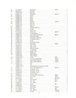
Page 13: ...M836 15 Key 5x5x20 1 16 JVM836 16 Cross Flat Head Screw M5x6 1 17 JVM836 17 Whitney Key 1 18 JVM836 18 Volume Spring 1 JVM836 18T Volume Spring 1 19 JVM836 19 Spring BrackeL 1 21 TS 1524011 Set Screw M8x8 1 22 TS 1514021 Hex Socket Cap Screw M6x15 4 2 JVM836 23 Transmission Sleeve 1 24 TS 1524011 Set Screw M8x8 1 25 JVM836 25 Round Pin 1 26 JVM836 26 Handle Base 1 JVM836 26T Handle Base 1 JVM836 2...

Page 14: ...ead Bolt 4 67 JVM836 67 Sleeve Pipe 4 68 JVM836 68 Castle Nut 4 69 JVM836 69 Rack Sleeve 1 JVM836 69T Rack Sleeve 1 70 JVM836 70 Cone point Set Screw M5x5 1 72 JVM836 72 Nut 1 JVM836 72T Nut 1 JVM836 72TA Nut Assembly Include 72 83 98 1 73 BB6206 Ball Bearing 6206 1 74 JVM836 74 Cross Flat Head Screw M5x10 1 75 JVM836 75 Nut 1 JVM836 75T Nut 1 JVM836 75TA NutAssembly Include 100 101 1 76 JVM836 76...

Page 15: ... JVM836 94 HeadBody 1 JVM836 94T HeadBody 1 95 JVM836 95 Cross RoundCapScrew M5x6 2 96 JVM836 96 Plate 1 97 JVM836 97 Cover 1 98 JVM836 98 Aluminum Block 04X3 2 100 JVM836 1 00 Aluminum Block 06X3 2 101 JVM836 1 01 Set Screw M8x8 2 102 JVM836 1 02 Set Screw M5x6 1 14 ...

Page 16: ...mber 0050104 and Higher 94 Q 92 dtp 22 31 fi 91_V I 2325 I 93 90 1 39 0 26 1 fA 11 ar o B7 43 1 d 1 17 I 56 0 18 44 00 d 62 84 oJ 102 0 QJ 57 950 85 J 86 Y 6 96 I 97 47 f f63 98 r 79 2 64 80 67 65 59 83 68 I I 70 I I V 81 82 71 1 83 15 ...

Page 17: ...4 Shaft 1 JVM836 14T Shaft 1 15 JVM836 15 Key 5x5x20 1 16 JVM836 16 Cross Flat Head Screw M5x6 1 17 JVM836 17 Whitney Key 1 18 JVM836 18 Volume Spring 1 JVM836 18T Volume Spring 1 19 JVM836 19 Spring Bracket 1 21 TS 1524011 Set Screw M8x8 1 22 TS 1514021 Hex Socket Cap Screw M6x15 4 23 JVM836 23 Transmission Sleeve 1 24 TS 1524011 Set Screw M8x8 1 25 JVM836 25 Round Pin 1 26 JVM836 26 Handle Base ...

Page 18: ...xible Handle 1 66 JVM836 66 T Head Bolt 4 67 JVM836 67 Sleeve Pipe 4 68 JVM836 68 Castle Nut 4 69 JVM836 69 Rack Sleeve 1 JVM836 69T Rack Sleeve 1 69 1 JVM836 69T 1 C Clip R62 1 70 JVM836 70 Cone point Set Screw M5x5 1 71 JVM836 71 Taper Roller Bearing 30206 1 71 1 JVM836 71 1 Taper Roller Bearing 32008 1 72 JVM836 72 Nut 1 JVM836 72T Nut 1 JVM836 72TA Nut Assembly Include 72 83 98 1 74 JVM836 74 ...

Page 19: ...94 JVM836 94 HeadBody 1 JVM836 94T HeadBody 1 95 JVM836 95 CrossRoundCap Screw M5x6 2 96 JVM836 96 Plate 1 97 JVM836 97 Cover 1 98 JVM836 98 AluminumBlock 04X3 2 102 JVM836 102 Set Screw M5x6 1 18 ...

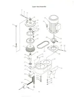
Page 20: ...3 2 Upper Head Assembly 23 17 29 30 J 19 1D11 20 in 34 42 41 40 39 I I 35 i 38 46 IT 37 36 19 ...

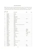
Page 21: ...l Bearing 6007ZZ 1 14 VM M2 Brake 1 VM M2T Brake 1 VM M2TA Brake Assembly Include 14 15 48 49 1 15 VM M1 Screw 1 VM M1T Screw 1 16 VM M6 Brake Disc 1 17 VM M8 Pulley 1 18 VM M11 Spindle Shaft 1 19 VM M7 Whitney Key 6x6x16 1 20 VM M9 Whitney Key 6X6X32 1 21 BB6007ZZ Ball Bearing 6007ZZ 1 22 VM M5 C Retaining Ring 062 1 23 VM M25 Motor 1 1 2HP 1 PH 1 VM M25 3Ph Motor 1 1 2HP 3 PH 1 24 VM M21 Hex Hea...

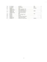
Page 22: ...3Ph Switch Assembly 3Ph 1 43 JVM836 43B Hex Socket Cap Screw M6x8 4 44 JVM836 44B Switch Cord 4C 1 Ph 1 JVM836 44 3Ph Switch Cord 6C 3Ph 1 45 VB A29 Belt A29 1 46 VM M26 Spindle Speed Chart 1 48 VM M2 1 Spring 2 49 VM M2 2 Cross Round Cap Screw 2 50 JVM836 U50 Plastic Electrical Box 1 51 JVM836 U51 Cross Round Cap Screw M5x40L 2 21 ...

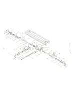
Page 23: ...15 N N 17 30 12 ij 1 5 4 2 3 r CD I c III CD IE III III CD 3 C ...

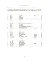
Page 24: ... 6 30 1 7 VM 16 Dial Holder 1 VM 16T Dial Holder 1 VM 16TA Dial HolderAssembly Include 4 5 7 30 1 8 VM 18 Bearing Retaining Cover 2 9 TS 1515011 Hex Socket Cap Screw M8x16 6 10 VM M26 Limit Plate 3 11 VM M26 1 River 6 12 BB6204 Ball Bearing 6204 5 14 VM 114 Bearing Bracket 1 15 VM 118 Bearing Bracket 1 16 VM J11 Bearing Block 1 17 VM 113 Hex Socket Screw M10x16 8 18 VM 112 Taper Pin 08x130 6 19 TS...

Page 25: ...N j 41 51 77 82 27 43 8 7 21 25 i 22 84 26 29 28 52 36 61 76 ...

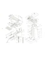
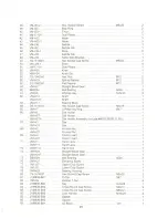
Page 26: ... 1 12 VM L1 Handle 1 VM L1T Handle 1 13 VM L3 PinionShaft 1 VM L3T Pinion Shaft 1 VM L3TA PinionShaft Assembly Include 11 12 13 1 14 VM L2 Full Dog Point Set Screw M6x12 1 16 TS 1550081 Flat Washer M12 4 17 VM K12 Stud S N 0040063 lower M12x105 4 VM K12N Stud S N 0040064 higher M12x115 4 18 JVM836 18B Adjustable Screw 6 19 TS 1523021 Set Screw M6x10 2 19 1 TS 1540041 Hex Nut M6 2 20 VM L4 Lock Han...

Page 27: ...rew M6x16 3 65 VM H7 C Retaining Ring 047 1 66 VM H5 Dial Holder 1 VM H5T Dial Holder 1 VM H5TA Dial HolderAssembly Include 66 67 68 69 71 90 1 67 VM H3 Dial 1 VM H3T Dial 1 68 VM H2 Knurled NuL 1 VM H2T Knurled Nut 1 69 VM H4 Clutch Insert 1 VM H4T Clutch Insert 1 71 VM H1 Hand Lever 1 VM H1T Hand Lever 1 73 VM H1 3 Hand Grip 1 74 VM H24 Straight Bevel Gear 1 VM H24T Straight Bevel Gear 1 75 BB62...

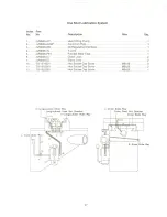
Page 28: ...e 1 6 JVM836 CJ Check Joint 2 7 JVM836 EJ Elbow Joint 2 10 TS 1514021 Hex Socket Cap Screw M6x16 4 11 TS 1503061 Hex Socket Cap Screw M6x25 2 12 TS 1503061 Hex Socket Cap Screw M6x25 1 B Longitudinal Slide Way Longitudinal Feed Nut Bracket F Longitudinal Slide Way I 1 I L Knee Slide ay I I 1 17 I I I I I I 1 I I I I I I I L 27 L Cross Slide Way Cross Feed Nut Bracket Cross Slide Way L I R Knee Shd...

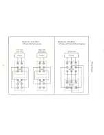
Page 29: ...les Wiring Diagram Low Volt 110 115V High Volt 220 230V 220V 230V Power Power Power j r l1 j r l1 i A t i I B CID I I 8 I I Q I I 00 1 I I 1 1 _I I Q c I I I I I II I II I I Switch I I witcll I 1 Swj ch I 1 1 11 11 1 1 3 L L r 1 Motor 1 111J I I L I Motor I r D 1 I I I I I I L ...

Page 30: ......

Page 31: ......

Page 32: ......

Reviews: