10
5. Standing on the
right side
of the band saw
(Figure 2), pull the motor towards you.
6. Place the
belt
(C, Fig. 5) around the
wheel
pulley
(B, Fig. 5) and
motor pulley
(A, Fig. 5).
7. Standing on the
right side
of the band saw,
push the motor away to put tension on the belt.
8. With a 6mm hex wrench, tighten both
socket
head cap screws
(D, Fig. 5).
Mounting the Switch
The switch is mounted to the saw body casting on
the front side of the saw between the upper and
lower doors.
Referring to Figure 6:
1. With a cross-point screwdriver, fasten the
switch
(A) to the
casting
(C) with the two
screws already on the switch box (B). These
screws also hold the
back plate
of the switch
box in place.
Note:
There are two mounting holes at the upper
screw location. Use the left mounting hole.
2. In the remaining top mounting hole, secure with
an M5x12
pan head screw
(E) and M5
gear
washer
.
3. Secure
the
electrical cords
(F) with a
wire clip
(G) and M5x12
pan head screw
(H).
Cord Clamp
Referring to Figure 7:
On the right side of the saw above the motor,
secure the
electrical cord
(A) that connects the
switch box to the motor with the
cord clamp
(B) and
M5x12
pan head screw
(C).
Figure 5
Figure 6
Figure 7
Summary of Contents for JWBS-14OS
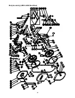
Page 22: ...22 Body Assembly JWBS 14OS Band Saw ...
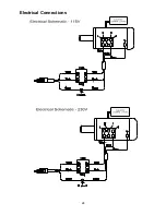
Page 24: ...24 Electrical Connections ...


