background image

11

Table Insert Adjustment

• 

Hardware: Table Insert

• 

Tools: 3mm Hex Wrench, Straight Edge

1.

Lower blade completely.

2.

Place the open end of the insert under the
splitter and lower the insert into the opening.

3.

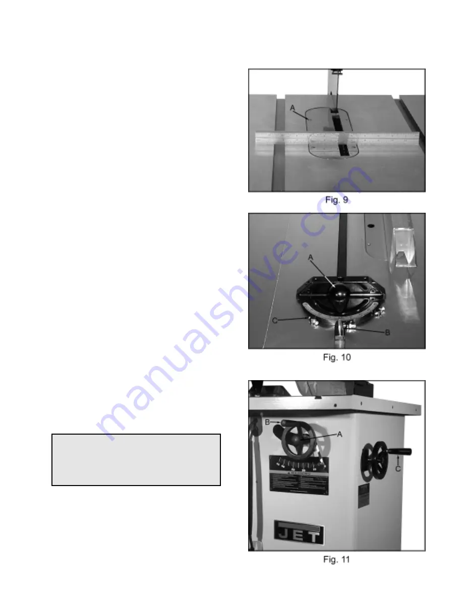
Adjust the table insert flush with the table by
turning four leveling screws (A, Fig. 9) and
using a straight edge.

Mounting Rails & Extension Table

With the extension wing properly aligned, the
rail and fence assembly can now be mounted to
the saw. See the Owner’s Manual for the
XACTA Fence Assembly Instructions. This will
address the mounting of the table, switch, rails
and fence.

Miter Gauge Operation

• 

Hardware: Miter Gauge

• 

Tools: Cross Point Screwdriver, 8mm Wrench

1.

Adjust miter gauge by loosening lock knob
(A, Fig. 10) and turning miter body to
desired angle. To move gauge beyond
index stops, flip down the stop (B, Fig. 10).

2.

Adjust index stops by turning one of three
adjustment screws (C, Fig. 10).

Note: Always make test cuts. Do not relay
solely on miter gauge indicator marks. There
are two holes in the miter gauge body that will
allow you to mount an wooden extension face.

Blade Raising and Tilting Mechanism

CAUTION

Never try to force the tilting mechanism past

the 45

°°°°

or 90

°°°°

stops! This may cause the

blade to go out of alignment!

1.

To raise or lower the saw blade, loosen lock
knob (A, Fig. 11), and turn handwheel (B,
Fig. 11) until desired height is reached.
Tighten lock knob. The blade should be
adjusted about 1/8" above the top surface of
the material being cut.

2.

To tilt the saw blade, loosen lock knob, turn
handwheel (C, Fig. 11) until desired angle is
obtained, then tighten lock knob.

Summary of Contents for JWCS-10A

Page 1: ...NUAL JWCS 10A Cabinet Saw JWCS 10A PF Shown JET EQUIPMENT TOOLS INC P O BOX 1349 Phone 253 351 6000 A WMH Company Auburn WA 98071 1349 Fax 1 800 274 6840 www jettools com e mail jet jettools com M 708...

Page 2: ...intenance JET LIMITS ALL IMPLIED WARRANTIES TO THE PERIOD SPECIFIED ABOVE FROM THE DATE THE PRODUCT WAS PURCHASED AT RETAIL EXCEPT AS STATED HEREIN ANY IMPLIED WARRANTIES OR MECHANTABILITY AND FITNESS...

Page 3: ...pply 13 Give your work undivided attention Looking around carrying on a conversation and horse play are careless acts that can result in serious injury 14 Keep visitors a safe distance from the work a...

Page 4: ...pment grounding conductor to a live terminal Check with a qualified electrician or service personnel if the grounding instructions are not completely understood or if in doubt as to whether the tool i...

Page 5: ...chment plug A supplied with the tablesaw must be replaced with a UL CSA listed plug suitable for 230V operation D Contact your local Authorized JET Service Center or qualified electrician for proper p...

Page 6: ...reakdown 15 Cabinet Table Assembly Parts List 16 17 Motor Trunnion Assembly Parts Breakdown 18 Motor Trunnion Assembly Parts List 19 20 Electrical Schematic 21 Specifications JWCS 10A Stock Number 708...

Page 7: ...bly 2 Handle Assemblies 1 Motor Cover Tools Included for Assembly 1 3mm Hex Wrench 1 Arbor Wrench Tools Required for Assembly Adjustments 1 8mm Box Wrench 1 10mm Box Wrench 1 13mm Box Wrench 1 14mm Bo...

Page 8: ...Cap Bolts 3 M10 Lock Washers 3 M10 Flat Washers 1 Extension Wing Tools 17mm Wrench Straight Edge 1 Mount the extension wing to table with three hex cap bolts three lock washers and three flat washers...

Page 9: ...ch and a Cross Point Screwdriver 1 Thread a M16 hex nut and M16 Lock Washer A Fig 5 completely onto the blade guard post B Fig 5 2 Thread blade guard post into trunnion at the rear of the saw Figure 5...

Page 10: ...on the arbor shaft making sure the teeth point down at the front of the saw Replace the flange and the arbor nut 4 Place a wood scrap in the blade s teeth Hold in such a way that if it slips or the bl...

Page 11: ...y loosening lock knob A Fig 10 and turning miter body to desired angle To move gauge beyond index stops flip down the stop B Fig 10 2 Adjust index stops by turning one of three adjustment screws C Fig...

Page 12: ...p screw B Fig 13 in or out The adjusting stop screw should stop against the end of the tilting screw C Fig 13 when the blade is 90 to the table Tighten lock nut 6 Place a square on the table after tur...

Page 13: ...red stop button on the switch assembly box In the event the saw stops operating due to the motor over heating wait until the motor cools down push the reset button on the motor and press the green st...

Page 14: ...not wired for correct voltage 1 Replace with adequate size cord 2 Contact your local electrical company 3 Refer to motor junction box Saw vibrates excessively 1 Stand on uneven floor 2 Damaged saw bla...

Page 15: ...15 Cabinet Table Assembly...

Page 16: ...3 ST039904 Tapping Screw M3 5x32 2 24 JCS10 9 JET Label 1 25 990805 Tapping Screw M4x10 2 26 TS 1490031 Hex Cap Bolt M8x20 4 27 TS 1551061 Lock Washer M8 4 28 TS 1550061 Flat Washer M8 4 29 290029 Str...

Page 17: ...M8 4 69 TS 1551061 Lock Washer M8 4 70 TS 1540061 Hex Nut M8 4 71 290146 Special Washer 4 72 290147 Foam Strip 1 73 200024 Splitter Bracket 1 74 200252 Arbor Wrench 1 75 200253 Hex Wrench 3mm 1 JWTS1...

Page 18: ...18 Motor Trunnion Assembly...

Page 19: ...r Washer 1 22 200070 Eccentric 1 23 TS 2310162 Hex Nut M16x1 5 1 24 200072 Pointer 1 25 TS 1523031 Set Screw M6x10 1 26 TS 1550071 Flat Washer M10 1 27 200075 Hand Wheel 1 28 200076 Handle 1 29 992313...

Page 20: ...ulley 1 69 992068 Key 5x5x40 1 70 TS 1523031 Set Screw M6x10 1 71 VB A30 V Belt A30 2 72 TS 1490041 Hex Cap Bolt M8x25 4 73 TS 1550061 Flat Washer M8 8 74 TS 1551061 Lock Washer M8 4 75 TS 1540061 Hex...

Page 21: ...21...

Reviews: