11
3.
If a ridge is visible where the drum overlaps,
lower table at outboard end (see sect. 8.4.1).
4.
Repeat this process until the ridge is eliminated
and entire board is sanded.
Note:
When sanding narrow stock (less than
254mm), return conveyor table to parallel position.
8.5
Tension roller adjustment
The infeed and outfeed rollers are tensioned to
provide downward pressure on the workpiece to
prevent slippage on the feed conveyor. Tension
rollers have been set by the manufacturer, but
should be inspected and may require adjustment as
the sander receives use.
Improperly adjusted tension
rollers (i.e. those set too high, rendering them non‐
functional) could allow kickback of pieces being
sanded.
Tension roller pressure may be increased or
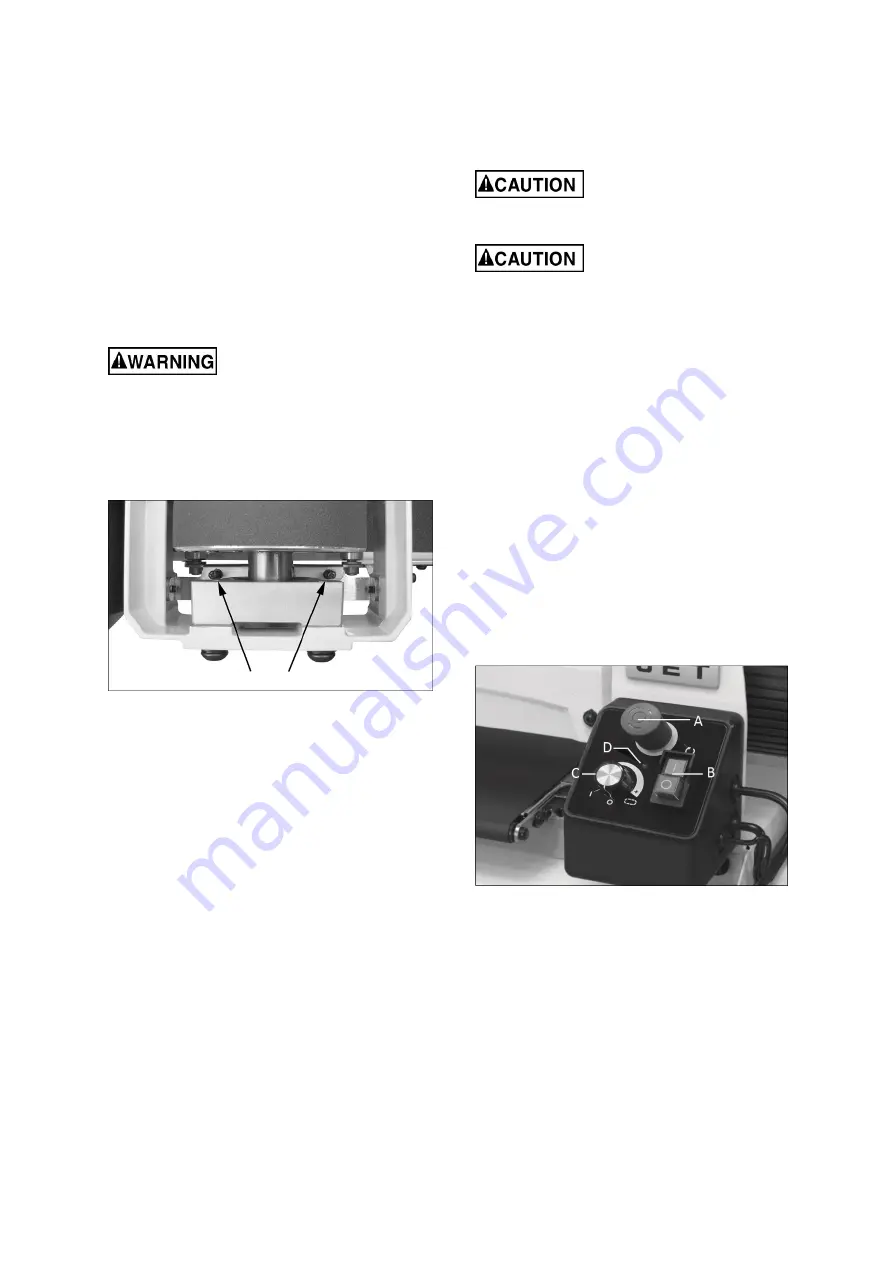
decreased by turning the screws on the tension roller
brackets (Figure 8‐4) at each end of drum.
Figure 8‐4: tension adjustment screws
Too much tension roller pressure can result in a
“snipe” mark, which is a visible line running across
the width of the board and located approximately
55mm from end of board.
If snipe occurs on the leading end of board, adjust
outfeed tension roller. If the snipe occurs on trailing
end of board, adjust infeed tension roller.
9.0
Operations
Before using your drum sander, review the previous
sections on initial set‐up and adjustment. Before
operating, make sure an abrasive strip is mounted
and a proper dust collection system is connected.
9.1
Basic Operating Procedure
1.
Establish depth of cut.
2.
Start dust collection system.
3.
Start sanding drum (with control panel switch,
Figure 9‐1).
4.
Start conveyor and select feed rate (with control
panel dial, Figure 9‐1).
5.
Feed stock through machine.
To feed stock through the sander, rest and hold
board to be sanded on conveyor belt, allowing
conveyor belt to carry board into drum. Once stock is
halfway through, reposition yourself to outfeed side
of machine to receive and control board as it exits.
Board will be forced down
against conveyor table as it begins feeding, causing
pinching hazard. Keep fingers away.
Do not open drum hood until
drum comes to a complete stop.
9.2
Drum & conveyor motor operation
1.
Connect power supply to machine.
2.
Disengage emergency stop by clockwise turning
the red button or pulling it up (A, Figure 9‐1).
Note: Error Indicator (D) may flash continuously to
remind that the conveyor speed dial is NOT set at
OFF position before starting the operation.
The
control system is designed to prevent the conveyor
belt from being activating accidentally. If conveyor
belt motor doesn’t work, turn the dial (C) to OFF and
re‐dial.
3.
Turn on the On/Off switch (B) to start drum
motor.
4.
Rotate conveyor speed dial (C) clockwise to start
and increase speed of conveyor.
Figure 9‐1: control panel
9.3
Circuit breaker reset
This sander is equipped with drum motor overload
protection. When the circuit trips because of
overload, allow a period of time for the motor to cool
down and then restart the machine.
9.4
Setting depth of cut
Adjusting the drum sander for proper contact
between abrasive and stock determines the depth of
cut. The depth of cut is controlled by the height
adjustment handle.


