background image


13 


the  tension  rollers.  Try  to  process  only  multiple 
pieces of similar thickness.  

If  there  is  a  significant  thickness  difference,  the 
thinner pieces can slip on the conveyor belt if they do 
not contact the tension rollers. Also note that pieces 
thicker  than  20mm  should  be  longer  than  the 
minimum normally recommended to prevent tipping 
of the stock. 

9.6.4  Edge sanding 

When  edge  sanding,  the  sander  will  mimic  the 
opposite  edge  of  the  stock  which  is  lying  on  the 
conveyor belt. Because of this, it is important for the 
stock  edge  to  have  been  ripped  at  the  proper  angle 
to  the  face  before  the  sanding  process.  When  edge 
sanding  stock  that  is  less  than  3/4”  wide  or  more 
than 2” high, it is good procedure to stack and clamp 
several  pieces  together  to  prevent  them  from 
slipping or tipping on the conveyor belt. 

9.6.5  Sanding imperfect stock 

When  sanding  stock  with  a  cup  or  crown,  place  the 
crown up. This will stabilize the stock to help prevent 
tipping  or  rocking  during  sanding.  After  the  crown 
has been removed and the top is flat, turn the stock 
over  and  sand  the  opposite  side.  To  avoid  personal 
injury,  take  special  care  when  sanding  stock  that  is 
twisted, bowed, or otherwise varies in thickness from 
end  to  end.  If  possible,  support  such  stock  as  it  is 
being sanded to keep it from slipping or tipping. Use 
extra  roller  stands,  help  from  another  person,  or 
hand  pressure  on  the  stock,  to  minimize  potentially 
hazardous situations. 

9.6.6  Face frames and raised panel doors 

It  is  very  important  to  have  the  proper  abrasive 
contact  when  doing  this  type  of  sanding.  If  the 
machine is set to take an excessive depth of cut, the 
result  can  be  a  gouge  or  dip  as  the  drum  goes  from 
sanding  the  rails  at  full  width  to  sanding  just  a  few 
inches  of  width  on  the  stiles.  To  prevent  this  make 
sure, when using abrasives finer than 80 grit, that the 
drum is in contact with the wood but can still be spun 
by  hand.  If  there  is  room,  angling  the  stock  on  the 
conveyor belt can also help.  

Slowing  the  conveyor  feed  when  coming  to  a  rail  in 
the stock can help prevent a dip or gouge. This allows 
the abrasive to work the wider width with less effort, 
and  to  achieve  better  consistency  of  the  finished 
surface. 

9.6.7  Stock feeding angle 

Some  pieces,  because  of  their  dimensions,  will  need 
to  be  fed  into  the  machine  at  a  90°  angle 
(perpendicular  to  drum).  However,  even  a  slight 
offset  angle  of  stock  will  provide  for  more  effective 
stock  removal.  The  optimum  feeding  angle  for  stock 
removal is about 60°.  

Angling  the  workpiece  for  stock  removal  provides 
other  advantages,  such  as  less  loading  of  certain 
areas of the drum due to glue lines or mineral streaks 

in  the  stock,  more  even  wear  of  abrasive  strips, 
potentially faster feed rates, and lighter loads on the 
motor. Note that to get the best final finish, however, 
the stock should be fed through the machine so it will 
be sanded in line with the grain of the wood on the 
final one or two passes. 


10.0  

User‐maintenance


 Before doing maintenance on the 

machine,  disconnect  it  from  the  electrical  supply 
(pull  out  the  plug),  unless  indicated  otherwise.  
Failure to comply may cause serious injury. 

10.1  

Cleaning and lubrication


For  best  results,  make  cleaning  the  sander  a  regular 
shop procedure. Allowing excess build‐up of dust and 
debris  can  adversely  affect  performance  through 
loading  of  the  abrasives,  slippage  on  the  conveyor 
table,  and/or  accumulation  of  material  inside  the 
drums which can throw off the centre of balance.  

Leave the dust collector on when cleaning dust from 
the  drums.  Also  brush  the  conveyor  belt  after 
cleaning operations. If not cleaned, the conveyor belt 
could allow stock to slip during sanding operations. 

NOTE:  Bearings  are  pre‐sealed  and  require  no 
lubrication. 


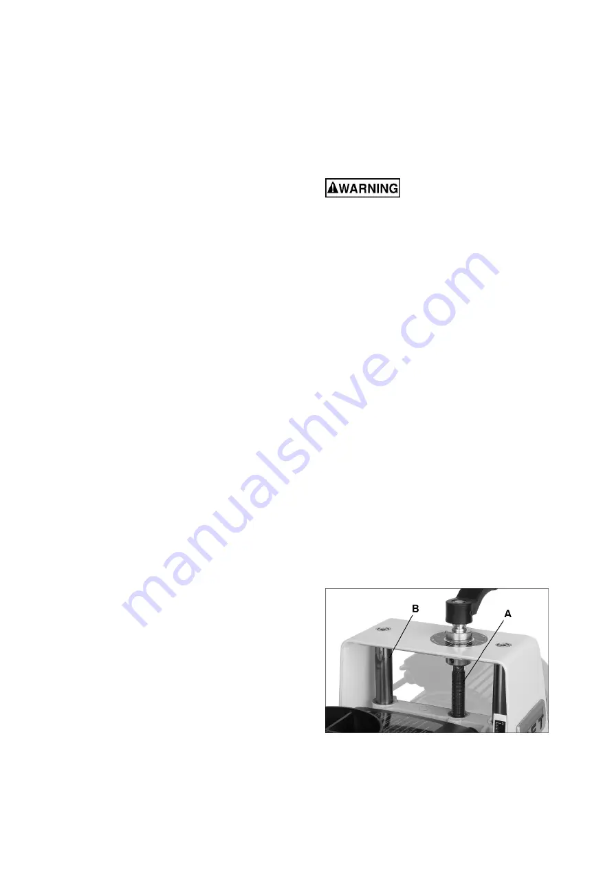
Lubricate elevating leadscrew (A, Figure 10‐1) as 
needed. 


Clean sanding dust from abrasive strip and brush 
dust from conveyor belt. 


Keep guide bars clean (B, Figure 10‐1). 


Blow  dust  from  motor  vents  and  switch  area. 
Blow  dust  from  inside  of  sanding  drum,  which 
may  cause  vibration  or  offset  the  centre  of 
balance. 


Check  all  screws  for  tightness  on  parts  such  as 
bearings, conveyor table, and couplings. 


Figure 10‐1 

10.2  

Drum maintenance


The  drum  should  not  require  removal  from  the 
machine  under  normal  circumstances.  Should 

Summary of Contents for JWDS-1020-M

Page 1: ...m Sander Zylinderschleifmaschine Ponceuse cylindre Original GB Operating Instructions D Gebrauchsanleitung F Mode d emploi TOOL FRANCE SARL 9 rue des Pyr n es F 91090 LISSES France www jettools com M...

Page 2: ...006 42 EC Machinery Directive Maschinenrichtlinie Directive Machines 2014 30 EU Electromagnetic compatibility elektromagnetische Vertr glichkeit compatibilit lectromagn tique designed in consideration...

Page 3: ...Features and Terminology 7 6 0 Setup and assembly 7 6 1 Shipping contents 7 6 2 Tools required for assembly 7 6 3 Handle 8 6 4 Mounting to workbench 8 6 5 Dust collection 8 6 6 Installing abrasives 8...

Page 4: ...zed technical rules concerning the operation of woodworking machines Any other use exceeds authorization In the event of unauthorized use of the machine the manufacturer renounces all liability and th...

Page 5: ...ion may be carried out by a qualified electrician only Have a damaged or worn power cord replaced immediately Make all machine adjustments or maintenance with the machine unplugged from the power sour...

Page 6: ...kness 3 0 8 mm Main materials Main body aluminium die casting and steel Drum extruded aluminium Conveyor table steel Drum height adjustment handle plastic Sanding Drum Drum dimensions L x Dia 257 x 12...

Page 7: ...and functions of the machine Figure 5 1 features and terminology Read and understand the entire contents of this manual before attempting set up or operation Failure to comply may cause serious injur...

Page 8: ...e from your drum sander An 80 grit 76mm wide abrasive strip is pre installed on the drum TIP If you are using an after market abrasive use a new JET supplied abrasive as a template to quickly cut a ne...

Page 9: ...pth scale indicates distance between bottom of sanding drum and top of conveyor belt Adjustment is performed by zeroing the scale 1 Unplug sander from power source 2 With an abrasive strip on drum low...

Page 10: ...tboard side of drum Figure 8 3 drum alignment 4 With hood open lower sanding drum while slowly rotating drum by hand until drum lightly contacts gauge NOTE Make sure gauge is contacted by the drum not...

Page 11: ...of cut 2 Start dust collection system 3 Start sanding drum with control panel switch Figure 9 1 4 Start conveyor and select feed rate with control panel dial Figure 9 1 5 Feed stock through machine T...

Page 12: ...used and whether the stock is fed directly in line with the conveyor table or at an angle If the drum motor is lugging down if conveyor belt is slipping or if you observe a ripple effect on the stock...

Page 13: ...a rail in the stock can help prevent a dip or gouge This allows the abrasive to work the wider width with less effort and to achieve better consistency of the finished surface 9 6 7 Stock feeding angl...

Page 14: ...centre conveyor belt on the conveyor table Then lay a straight edge on the exposed edge of conveyor table on left outboard side extending it over the roller Note distance between roller and straighte...

Page 15: ...e which will not accept stains evenly This will vary by type of wood Oak for example is susceptible to burnishing because of its open pores 11 2 Cleaning abrasive strips Regularly clean the abrasive s...

Page 16: ...erminals or worn insulation Low voltage Correct low voltage conditions Incorrect fuse or circuit breaker in power line Install correct fuse or circuit breaker Loud repetitive noise or vibration coming...

Page 17: ...conveyor belt Replace conveyor belt Ripples in sanded surface A Non uniformly spaced ripples B Uniformly spaced ripples A Uneven feed rate Conveyor belt slipping see above Board slips on conveyor belt...

Page 18: ...ositionen 21 4 0 Technische Daten 22 5 0 Merkmale und verwendete Terminologie 23 6 0 Einrichtung und Montage 23 6 1 Lieferumfang 23 6 2 F r die Montage ben tigte Werkzeuge 23 6 3 Kurbel 24 6 4 Montage...

Page 19: ...aschine m ssen alle Sicherheitsmechanismen und Sicherheitsabdeckungen funktionst chtig und korrekt montiert sein Zus tzlich zu den in dieser Betriebsanleitung aufgef hrten Sicherheitsma nahmen und den...

Page 20: ...ebung eingesetzt werden und darf keinem Regen ausgesetzt werden Schleifstaub ist explosiv und kann dar ber hinaus auch ein Gesundheitsrisiko darstellen Es muss stets eine geeignete Staubabsaugvorricht...

Page 21: ...ufgrund eines Stromschlags kommen 3 4 Schilder und ihre Positionen A Sicherheitswarnung B Laufrichtung von Schleiftrommel und Vorschubband C Tischverriegelung vor dem Parallelausrichten l sen Fig A Fi...

Page 22: ...f Schleiftrommel Trommelabmessungen Durchmesser 127mm x 257mm Trommeldrehzahl 1400 min Installiertes Schleifband K rnung 80 76mm breit Aluminiumoxid Korund Trommelhebung pro Handraddrehung 1 6 mm Vors...

Page 23: ...machen k nnen Abbildung 5 1 Merkmale und Terminologie Vor Montage und Inbetriebnahme muss die Bedienungsanleitung vollst ndig durchgelesen und verstanden werden Nichtbeachtung kann zu schweren Verlet...

Page 24: ...ng des Schleifbands auf der Trommel ist wichtig Ein 76 mm breites Schleifband mit 80er K rnung ist an der Trommel vorinstalliert TIPP das von JET original gelieferte Schleifband als Vorlage f r das Zu...

Page 25: ...rehen um die Trommel abzusenken und entgegen um sie anzuheben Eine Umdrehung der Kurbel bewirkt eine Bewegung von ca 1 6 mm eine Vierteldrehung etwa 0 4 mm 8 2 Dickenskala Die Dickenskala gibt den Abs...

Page 26: ...nen 2 Die Absaughaube ffnen und das Schleifband von der Trommel entfernen 3 Die Lehre F Abb 8 3 auf der Au enseite der Trommel zwischen Trommel und Vorschubtisch einf hren Abb 8 3 Trommelausrichtung 4...

Page 27: ...hw cher eingestellt werden 9 0 Bedienung und Betrieb Vor der Verwendung der Zylinderschleifmaschine die vorangehenden Abschnitte zur Einstellung noch einmal lesen Sicherstellen dass ein Schleifband an...

Page 28: ...ginnen Sie probeweise mit ca 50 der maximalen Vorschubgeschwindigkeit Die Wahl der am besten geeigneten Vorschubgeschwindigkeit h ngt von einer Reihe von Faktoren ab Dazu geh ren Schleifguttyp K rnung...

Page 29: ...tzen 9 6 6 Rahmen und Kassettent ren Ein durchgehender Schleifkontakt ist wichtig Wird die Maschine auf eine zu gro e Schleiftiefe eingestellt kann dies zu starken Absenkungen f hren Absenkungen oder...

Page 30: ...llen Abbildung 10 3 Vorschubbandwechsel Hinweis L uft das Vorschubband kontinuierlich zu einer Seite der Maschine hin kann ein Seitentausch des Vorschubbandes dieses Problem beheben berpr fen Sie mit...

Page 31: ...die ffnung hineindr cken bis der Messingclip einrastet und fest sitzt 6 Die B rstenkappe anbringen 7 Den Vorgang f r die andere B rste wiederholen HINWEIS Zum Einlaufen der neuen B rsten den Vorschub...

Page 32: ...fgenommen werden Dies ist je nach Holzart unterschiedlich Eichenholz beispielweise ist aufgrund seiner offenen Poren besonders anf llig 11 2 Schleifmittel reinigen Das Schleifband auf der Trommel rege...

Page 33: ...ne Klemmen oder abgenutzte Isolierung berpr fen Spannung zu niedrig Spannungsbedingungen korrigieren Falsche Sicherung oder falscher Trennschalter in Netzleitung Korrekte Sicherung bzw korrekten Trenn...

Page 34: ...en Vorschubgeschwindigkeit zu hoch Vorschubgeschwindigkeit verringern Vorschubband verschmutzt oder verschlissen Das Vorschubband absaugen reinigen oder auswechseln Geschliffene Fl che ist wellig A We...

Page 35: ...exp dition 40 6 2 Outils n cessaires au montage 40 6 3 Poign e 40 6 4 Montage de la ponceuse sur la table 40 6 5 Collecte des poussi res 40 6 6 Installation des abrasifs 40 7 0 Connexions lectriques...

Page 36: ...icables votre pays Toute autre utilisation est strictement interdite En cas d usage non autoris le fabricant renonce toute responsabilit qui est transf r e l op rateur 3 2 Consignes de s curit g n ral...

Page 37: ...ation lectrique doivent tre uniquement effectu s par un lectricien qualifi Remplacez imm diatement un cordon d alimentation us ou endommag R alisez tous les r glages de la machine ou la maintenance av...

Page 38: ...ximum de la plaque deux passages 508 mm Epaisseur maximum de la plaque 76 mm Longueur minimum de la plaque 60 mm Epaisseur minimum de la plaque 3 0 8 mm Mat riaux Chariot et bo tier Aluminium et acier...

Page 39: ...mposants principaux et les caract ristiques de la ponceuse JWDS 1020 M Ceux ci sont r f renc s dans tout le manuel et vous aideront vous familiariser avec les fonctions et op ration de la machine Figu...

Page 40: ...compris 6 6 Installation des abrasifs Une fixation appropri e de la bande abrasive au cylindre est essentielle pour obtenir les meilleurs rendements de votre ponceuse cylindre Une bande abrasive de 7...

Page 41: ...x pr valent sur les recommandations 8 0 R glages 8 1 Contr le de la hauteur du cylindre La hauteur de la profondeur du cylindre de coupe est contr l e par la poign e de r glage de hauteur voir Figure...

Page 42: ...ux vis A figure 8 2 et serrez la vis de tension B figure 8 2 de ce c t Remarque Tournez la vis de tension d 1 4 de tour seulement ce moment Laissez la courroie un temps de r action au r glage avant de...

Page 43: ...r un glissement sur le convoyeur d alimentation Les rouleaux de tension ont t r gl s par le fabricant mais ils doivent tre v rifi s et peuvent n cessiter un r glage la r ception de la ponceuse Des rou...

Page 44: ...caoutchouc sur le support pour aider stabiliser la pi ce usiner par simple friction 9 5 D termination de la hauteur du cylindre Principe de base si pon age avec grains plus fins que 80 1 Pour tablir l...

Page 45: ...ent glisser de la courroie transporteuse si elles ne sont pas en contact avec les rouleaux de tension Aussi remarquez que les pi ces plus paisses de 20 mm doivent tre plus longues que le minimum norma...

Page 46: ...rieur du cylindre poncer car cela peut provoquer des vibrations ou un d calage du centre d quilibre V rifiez si toutes les vis de r glage des paliers table du convoyeur et accouplements sont bien serr...

Page 47: ...re des sympt mes de balais de carbone us s Si un balai est us remplacez les deux balais en m me temps Une utilisation continue de balais us s ou endommag s peut entra ner des dommages sur l armature d...

Page 48: ...2 Nettoyage des bandes abrasives Nettoyez r guli rement la bande abrasive de cylindre avec des b tonnets de nettoyage vendus dans le commerce tout en suivant les instructions du fabricant Lors du net...

Page 49: ...ifiez les fixations et resserrez si n cessaire Le ventilateur du moteur cogne le couvercle Serrez le ventilateur ou calez le couvercle du ventilateur Machine pas niveau Placez la ponceuse sur un sol p...

Page 50: ...e Ondulations sur la surface ponc e A Ondulations non espac es uniform ment B Ondulations espac es uniform ment A Vitesse d avance irr guli re Glissement de la courroie transporteuse voir ci dessus La...

Page 51: ...This page is intentionally blank...

Page 52: ...TOOL FRANCE SARL 9 Rue des Pyr n es F 91090 LISSES France...

Reviews: