9
6.
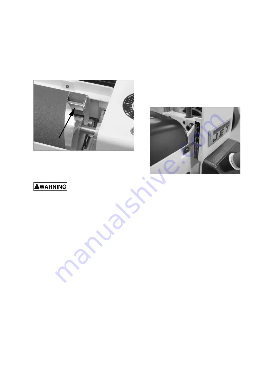
Press inboard take‐up lever (Figure 6‐6) and
insert trailing end of strip as far as it will go. If
necessary, trim tapered end of abrasive strip.
7.
Release inboard take‐up lever to secure strip.
All abrasive strips will stretch over time as they are
used, and may stretch enough to allow the take‐up
lever to reach its lowest position so that it cannot
maintain tension on the strip. If this occurs, follow
the above procedures to reset the take‐up lever.
Figure 6‐6
7.0
Electrical connections
All electrical connections must be
done by a qualified electrician in compliance with all
local codes and ordinances. Failure to comply may
result in serious injury.
The JWDS‐1020 Sander is rated at 230‐Volt power
only. The sander comes with a plug designed for use
on a circuit with a
grounded outlet.
Before
connecting to power source, be sure switch is in
off
position.
It is recommended that the sander be connected to a
dedicated 16 amp circuit with circuit breaker or fuse.
If connected to a circuit protected by fuses, use time
delay fuse marked “D”.
Local codes take precedence
over recommendations.
8.0
Adjustments
8.1
Drum Height Control
Drum height and depth of cut are controlled by the
height adjustment handle (see Figure 6‐1). Rotating
handle clockwise lowers drum, counter clockwise
raises it. One revolution of handle will move drum
approximately 1.6mm (or 1/4 turn = approx. 0.4mm),
as shown on the label below handle.
8.2
Depth scale
The depth scale indicates distance between bottom
of sanding drum and top of conveyor belt.
Adjustment is performed by “zeroing” the scale.
1.
Unplug sander from power source.
2.
With an abrasive strip on drum, lower drum to
where it touches top of conveyor belt. Note:
Make sure drum contacts belt, not just the feed
rollers.
3.
At this drum position, the (top edge of) depth
scale pointer should align with zero mark on
scale. If it does not, loosen screw (Figure 8‐1)
and shift pointer to align with zero.
4.
Retighten screw.
Note:
Depending on desired accuracy, you may need
to repeat this process when installing different
abrasive grits.
Figure 8‐1: depth scale adjustment
8.3
Conveyor belt tension and tracking
Conveyor belt tension adjustment may be necessary
during the break‐in period to compensate for belt
stretching, and also after long‐term use.
8.3.1 Belt tension adjustment
NOTE: Insufficient belt tension will cause slippage of
conveyor belt on drive roller during sanding
operation. The conveyor belt is too loose if it can be
stopped by hand pressure applied directly to top of
moving conveyor belt. Excessive belt tension can
result in bent rollers, bent brackets, and/or
premature wearing of bushings or conveyor belt.
To adjust conveyor belt tension:
1.
Slightly loosen four screws (A, Figure 8‐2) on
infeed side of conveyor, with 4mm hex wrench
(two screws on each side).
2.
Turn take‐up screw (B, Figure 8‐2) with 5mm hex
wrench. Do this on
both sides
of conveyor to
obtain approximately equal tension on both
sides of sanding belt when taut.
3.
Tighten four screws (A, Figure 8‐2).
4.
Check conveyor belt tracking before operating
machine. Proceed to
sect. 8.3.2
.


