


17
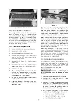
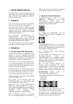
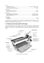
Figure 10‐2: maintenance areas
10.2
Drum elevation adjustment
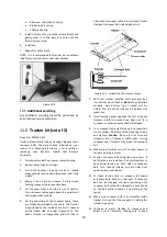
If the height control mechanism does not operate
easily or smoothly or there is excessive vertical
movement or deflection of the drum carriage tighten
all four (4) lock nuts (D, Figure 10‐1) and then loosen
them 1/8 to 1/4 turn. If the lock nuts are set too tight,
height control will not operate easily. If the lock nuts
are too loose, excessive deflection of the outboard
end of the drum carriage will result.
10.3
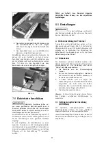
Conveyor belt replacement
1.
Disconnect sander from power source/unplug.
2.
Raise drum to highest position.
3.
Remove infeed/outfeed tables, if installed.
4.
Turn take‐up screws (Figure 8‐3) on both sides of
conveyor to relieve belt tension, and slide the
driven roller fully inward.
5.
Remove two (2) screws that attach conveyor
table to base.
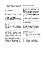
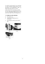
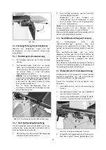
6.
Remove two (2) screws that attach conveyor
table to drum alignment bracket (E, Figure 10‐3).
7.
Loosen two locks (F).
8.
Lift up conveyor table and remove it from
machine. Avoid tearing the belt on any edges
underneath the conveyor table.
Do not allow the
Trackers to drop, as they may break.
9.
Set conveyor on motor side and slide conveyor
belt off end of conveyor table.
10.
Install new belt along with trackers (see
sect.
11.0
), and re‐install conveyor table. Tension and
track the new belt.
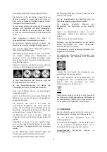
Figure 10‐3
Note:
If conveyor belt continually tracks to one side
of the machine, reversing the belt on the conveyor
table may remedy the problem. To make sure the
conveyor table is not twisted, place a level on the
conveyor table. Level the machine if needed. If there
is still a problem, proceed with the steps below:
Step 1
: Check conveyor drive roller and driven roller
to make sure they are parallel to surface of conveyor
table. To do this, first center conveyor belt on the
conveyor table. Then lay a straight‐edge on the
exposed edge of conveyor table on left (outboard)
side, extending it over the roller. Note distance
between roller and straightedge.
Step 2:
Now repeat Step 1 on right (inboard) side of
conveyor. Compare the measurements from side to
side. If they are not equal, loosen one of the brackets
that hold the roller in place. Tip this bracket until
distance between roller and straight‐edge are equal
from side to side, then tighten bracket.
10.4
Commutator brush inspection
To maintain motor efficiency, inspect the two carbon
brushes every two months, or more frequently if
sander is heavily used. Stalling or loss of power may
be a symptom of worn carbon brushes. If one brush is
worn out, replace both at the same time.
Continued use of damaged or
worn brushes may result in damage to motor
armature.
1.
Disconnect sander from power source/unplug.
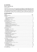
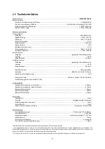
2.
Unscrew and remove cap with flat blade
screwdriver. See Figure 10‐4.
3.
Gently pry up an edge of the brass clip, until the
spring causes it to disengage from hole. (Notice
orientation of brush as you remove it; it should
be inserted in the same manner; curvature of
brush will match curvature of motor.)
4.
Pull out brush and inspect. Brush should be
replaced if any of the following are discovered:
Brush has worn to about 13mm long.
Signs of crumbling, burning or breaking.
End of brush is rough or pitted.


