11
7.0
Adjustments
7.1
Belt tension/replacement
Inspect belt tension frequently during the first few
hours of operation, as new belts may stretch during
this period. If the belt requires tightening, proceed
as follows:
1. Disconnect planer from power source.
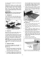
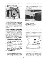
2. Remove side panel and belt guard. See Figure
7-1.
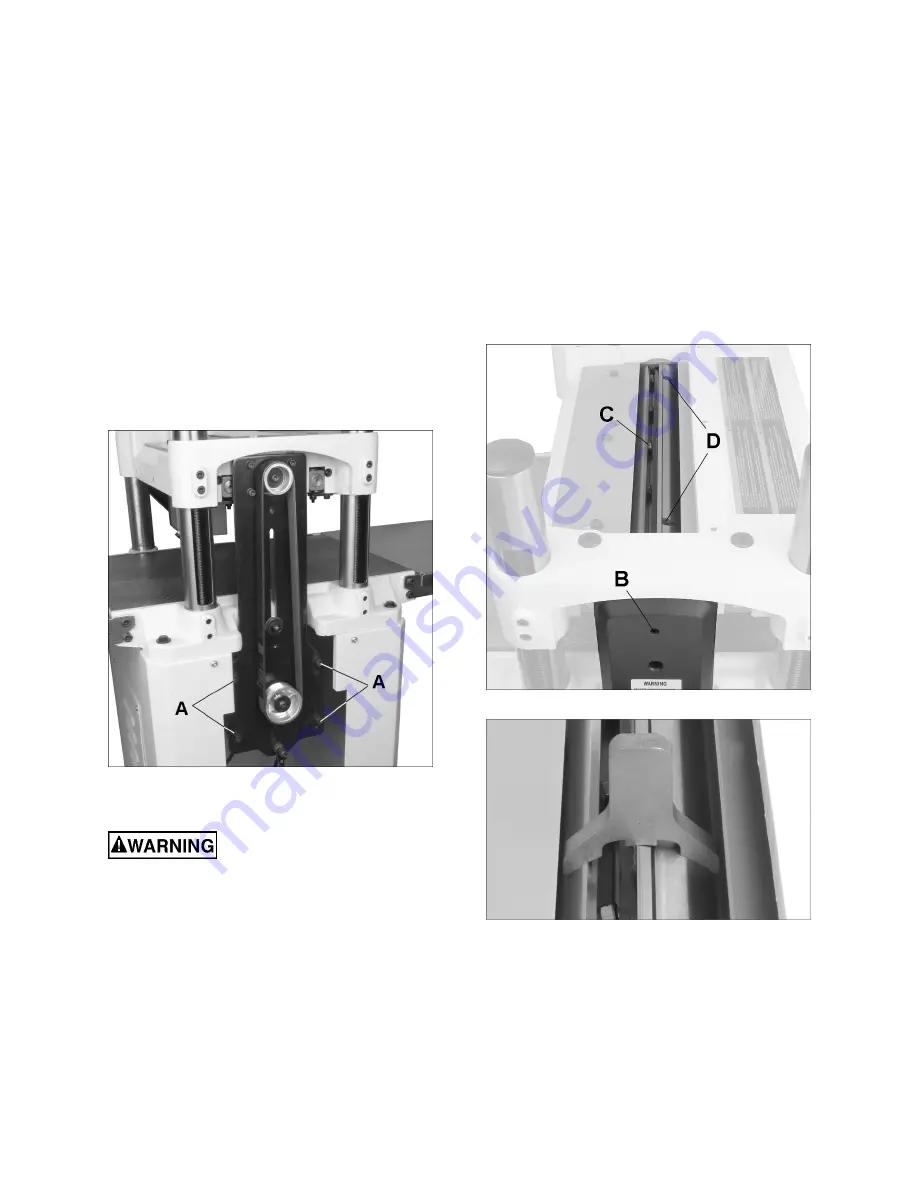
3. Loosen four socket hd cap screws (A, Figure 7-
1) with 6mm hex wrench, and lower motor
slightly until belt is tensioned.
4. Proper tension is achieved when there is about
1/2-inch deflection in the belt midway between
the pulleys, using moderate finger pressure.
5. Tighten screws (A), and reinstall belt guard and
side panel.
Figure 7-1
7.2
Replacing knives (JWP-15B only)
Use caution and proceed slowly
when working with and around the knives – they
are extremely sharp.
When dull knives are replaced, care must be
exercised in setting the new knives into the
cutterhead. The following procedure will ensure a
proper setting of knives on the JWP-15B Planer.
1. Disconnect machine from power source.
2. Remove dust hood and top cover.
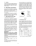
3. Insert the provided Torx driver (C, Figure 5-1)
into hole through belt guard (B, Figure 7-2). Use
this to rotate the cutterhead during the
procedure.
CAUTION:
Always remove hex wrench
before starting planer.
4. Loosen the five gib screws (C, Figure 7-2) with
a 12mm wrench.
5. Use the magnetic inserts in the Torx drive
handle to lift the knife out of the slot. Clean the
slot of any dust or pitch.
6. Place the new knife into the cutterhead slot.
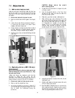
7. Place knife gauge onto cutterhead. The knife
should just contact the gauge and the gauge sit
flush on the cutterhead, as shown in Figure 7-
3. If adjustment is needed, turn screws (D,
Figure 7-2) in or out with a 3mm hex wrench,
until the knife contacts the gauge. Verify this
positioning at several points along the knife.
Figure 7-2
Figure 7-3
8. Snug the gib screws to secure the knife; do not
fully tighten yet.
9. Rotate cutterhead and repeat process for each
of the remaining two knives.
10. Now fully tighten all gib screws on one knife. Do
this in sequential order, beginning at one end of
the knife and working your way across to the
other end, tightening each screw in turn.
Summary of Contents for JWP-15B
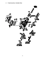
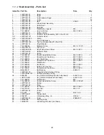
Page 21: ...21 11 1 1 Head Assembly Exploded View ...
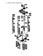
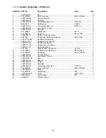
Page 23: ...23 11 2 1 Column Assembly Exploded View ...
Page 26: ...26 11 4 1 Gear Box Assembly Exploded View ...
Page 28: ...28 11 5 1 Cabinet Assembly Exploded View ...
Page 32: ...32 12 0 Electrical Connections for JWP 15B 15BHH ...
Page 34: ...34 This page intentionally left blank ...
Page 35: ...35 This page intentionally left blank ...
Page 36: ...36 427 New Sanford Road LaVergne Tennessee 37086 Phone 800 274 6848 www jettools com ...


