background image


34

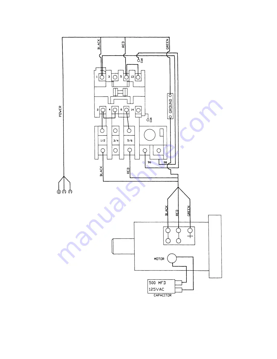
Electrical Connections 


Summary of Contents for JWP-15DX

Page 1: ...ructions and Parts Manual 15 inch Thickness Planer Model JWP 15DX WMH TOOL GROUP 2420 Vantage Drive Elgin Illinois 60124 Part No M 708538 Ph 800 274 6848 Revision A1 8 06 www wmhtoolgroup com Copyright WMH Tool Group ...

Page 2: ...postage prepaid to a location designated by us For the name of the location nearest you please call 1 800 274 6848 You must provide proof of initial purchase date and an explanation of the complaint must accompany the merchandise If our inspection discloses a defect we will repair or replace the product or refund the purchase price at our option We will return the repaired product or replacement a...

Page 3: ...ransmitting Rollers of Your Planer 14 Anti Kickback Fingers 14 Infeed and Outfeed Roller Spring Tension 15 Height of Infeed Roller Chipbreaker and Outfeed Roller 15 Outfeed Roller Height 16 Infeed Roller Height 16 Chipbreaker Height 16 Chip Deflector 17 Feed Speed Control 17 Stock Return Rollers 17 Depth of Cut 18 Maintenance 18 Lubrication 18 Troubleshooting Performance Problems 20 Troubleshootin...

Page 4: ...senic and chromium from chemically treated lumber Your risk of exposure varies depending on how often you do this type of work To reduce your exposure to these chemicals work in a well ventilated area and work with approved safety equipment such as face or dust masks that are specifically designed to filter out microscopic particles 10 Do not operate this machine while tired or under the influence...

Page 5: ... best and safest performance Follow instructions for lubricating and changing accessories 27 Make sure the workpiece is securely attached or clamped to the table Never use your hand to hold the work piece 28 Turn off the machine and disconnect from power before cleaning Use a brush or compressed air to remove chips or debris do not use your hands 29 Do not stand on the machine Serious injury could...

Page 6: ...reached at our web site www wmhtoolgroup com Specifications Model Number JWP 15DX Stock Number 708538 Maximum Cutting Width in 14 7 8 Maximum Cutting Thickness in 6 Full Width Cutting Depth in 1 8 Maximum Cutting Depth in 3 16 Minimum Planing Length in 8 Number of Knives 3 Cutterhead Speed RPM 4 500 Cuts Per Minute 13 500 Cutterhead Diameter in 2 7 8 Feed Rate FPM 16 and 20 Dust Chute Diameter in ...

Page 7: ...ion manual thoroughly for assembly maintenance and safety instructions Contents of the Shipping Container 1 Planer 1 Dust Hood 2 Extension Tables 1 Handwheel 1 Handle 2 Magnet Tools 4 Hex Wrenches 3 4 5 and 6mm 1 T handle Hex Wrench 4mm 3 Open end Wrenches 8 10 12 14 14 17 3 Bags of Fasteners see below 1 Owner s Manual 1 Warranty Card Contents of fastener bags Figure 2 A for installing Handwheel 1...

Page 8: ... be removed with a soft cloth moistened with a good commercial solvent Do not use acetone gasoline lacquer thinner or other solvents with a low flash point Do not use an abrasive pad because it may scratch the polished cast iron surfaces Use care when cleaning around the cutterhead area knives are extremely sharp Handwheel 1 Place the key into the slot on the shaft Figure 5 and mount the handwheel...

Page 9: ...nd screw them in or out as needed until tables are level 4 Securely tighten the hex cap screws 5 Mount the second extension table to the opposite side of the planer table using the same procedure Dust Hood Mount the hood to the rear of the head casting with six M6 x 12 hex washer head screws A Figure 8 It is strongly recommended that you use a dust collection system with this planer If you are not...

Page 10: ...ect the equipment grounding conductor to a live terminal Check with a qualified electrician or service personnel if the grounding instructions are not completely understood or if in doubt as to whether the tool is properly grounded Extension Cords The use of an extension cord is not recommended for this machine but if one is necessary make sure the cord rating is suitable for the amperage listed o...

Page 11: ...e belt tension 4 Proper tension is achieved when there is slight deflection in the belt midway between the pulleys using moderate finger pressure 5 Tighten the bottom nut on the adjustment screw Figure 11 Pulley Alignment The pulleys should be in line for proper belt operation 1 Remove the belt guard and place a straight edge against the faces of both pulleys Figure 12 2 If the straight edge does ...

Page 12: ...nch and turn the eccentric shafts B Figure 14 to raise or lower the rollers 4 When proper height is achieved tighten set screws 5 Adjust the rollers from the opposite side of the table in the same manner IMPORTANT Be sure that the height of front and rear rollers are the same And the table rollers must always be set parallel to the table Cutterhead Although your planer was carefully adjusted at th...

Page 13: ...t parallel to the cutterhead at the factory and no further adjustment should be necessary If your machine is planing a taper first check to see if the knives are set properly in the cutterhead Then check to see if the work table is set parallel to the cutterhead Proceed as follows 1 Disconnect machine from power source 2 Place the gauge block Figure 18 on the work table directly under the edge of ...

Page 14: ...ner of the base that you need to adjust 5 Turn the sprocket by hand to bring that corner into adjustment with the other three corners NOTE Turning sprocket clockwise will increase the distance between the working table and the head casting counterclockwise will decrease the distance This adjustment is very sensitive and it should not be necessary to turn the sprocket more than one or two teeth 6 W...

Page 15: ...urn decreases tension Adjust the screws at the other end of the rollers with the same number of turns Figure 23 Height of Infeed Roller Chipbreaker and Outfeed Roller The infeed roller chipbreaker and outfeed roller are adjusted at the factory The height relationship between these items and the cutterhead is crucial for accurate and safe planing The infeed roller chipbreaker and outfeed roller sho...

Page 16: ...ler just touches the gauge block Then tighten lock nut J Figure 26 6 Check and adjust the opposite end of the outfeed roller in the same manner Infeed Roller Height Use the exact same procedure for checking the infeed roller as you did for the outfeed roller Use the 02 0 5mm feeler gauge atop the gauge block If adjustment is necessary use the lock nut and screw on each end of the infeed roller Chi...

Page 17: ...nd sprockets for example when performing maintenance proceed as follows 1 You may find it easier to remove the sprocket guard by first removing the handwheel from the machine though this is not mandatory 2 Remove the socket head cap screw from the center of the cover using a 6mm hex wrench Remove the left triangular back plate 2 screws using a 10mm wrench See Figure 29 3 Pull the sprocket guard of...

Page 18: ...llers and table with a soft rag and non flammable solvent Periodically check all the chains for proper tension and adjust accordingly if needed The table should be kept clean and free of rust Some users prefer a paste wax on exposed steel and cast iron surfaces The wax provides a layer of protection as well as reducing friction between lumber and the table making cuts faster and smoother Avoid any...

Page 19: ...ox When operated more than 2 500 hours 70 to 90 weight oil 32 3 Return Rollers Inspect frequently SAE 30 33 4 Worm Gear Inspect and lubricate monthly Grease 34 5 Lead Screw Inspect and lubricate monthly Grease 34 6 Column Inspect and lubricate weekly Clean columns and apply SAE 30 34 7 Table Chain Inspect monthly lubricate when needed Grease or good quality bicycle chain lubricant 35 8 Feed Roller...

Page 20: ...nives Replace knives Too heavy a cut Adjust proper depth of cut Knives cutting against grain Cut along the grain Torn grain Dull knives Replace knives Dull knives Replace knives Too heavy a cut Adjust proper depth Rough Raised grain Moisture content too high Remove moisture by drying or use different stock Dull knives Replace knives Feed speed too slow Increase speed Rounded glossy surface Cutting...

Page 21: ... inside the electrical box Planer frequently trips One cause of overloading trips which are not electrical in nature is too heavy a cut The solution is to take a lighter cut If too deep a cut is not the problem then check the amp setting on the overload relay Match the full load amps on the motor as noted on the motor plate If amp setting is correct then there is probably a loose electrical lead C...

Page 22: ...c motor is suspect you have two options Have a qualified electrician test the motor for function or remove the motor and take it to a qualified electric motor repair shop and have it tested Miswiring of the machine Double check to confirm all electrical connections are correct and tight Refer to wiring diagram on page 34 to make any needed corrections Machine will not start restart or repeatedly t...

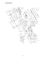
Page 23: ...23 Head Assembly ...

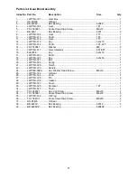
Page 24: ...cket 1 28 TS 0680021 Washer 1 4 2 29 TS 1482031 Hex Cap Screw M6x16 2 30 JWP15H 030 Outfeed Roller 1 31 JWP15H 031 Sprocket 1 32 JWP15H 032 Locking Bolt 1 33 JWP15H 033 Retaining Ring STW 12 1 34 JWP15H 034 Chipbreaker 1 35 TS 1540081 Hex Nut M12 1 36 JWP15H 036 Plate Spring 3 38 JWP208 038A Hex Washer Head Screw M6x12 23 39 JWP15H 039 Shaft 1 40 JWP15H 040 Deflector Plate 1 41 JWP15H 041 Anti Kic...

Page 25: ...21 Socket Head Cap Screw M6x10 4 77 PF C26 Washer 4 78 PA C56 Stud 1 79 PA C57 Idle Pulley 1 80 PA C58 Bracket 1 81 PA C59 Stud 1 82 PA C60 Hanger 1 83 PA C61 Spring 1 84 PA C62 Washer 1 85 JWP15H 076 Switch Bracket 1 86 JWP15H 077 Switch 1 88 TS 081C102 Screw 10 24X1 3 4 2 89 JWP15H 079 Tooth Washer 2 90 TS 0560071 Hex Nut 10 24 2 91 PF C27 Direction Indicator Label 1 92 PA C67 Label 1 93 PA G18 ...

Page 26: ...26 Base Assembly ...

Page 27: ...H 211 Gear 1 12 JWP15H 212 Retaining Ring STW 10 1 13 BB 6202Z Ball Bearing 6202Z 4 14 JWP15H 214 Retaining Ring RTW 35 4 15 JWP15H 216 Sprocket 4 16 TS 1550071 Washer M10 4 17 TS 1540072 Nut M10x1 25P 4 18 TS 1550061 Washer M8 2 19 TS 1490041 Hex Cap Screw M8x25 2 20 JWP15H 221 Bracket 1 21 JWP15H 222 Shaft 1 22 JWP15H 223 Sprocket 1 23 JWP15H 224 Retaining Ring STW 15 1 24 JWP15H 225 Chain 1 25 ...

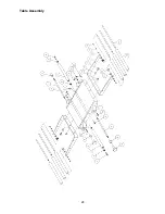
Page 28: ...28 Table Assembly ...

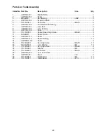
Page 29: ...5H 108 Lock Bushing 2 9 JWP15H 109 Knob 2 10 TS 1503051 Socket Head Cap Screw M6x20 8 11 PJ020801 Roller Frame 2 12 JWP15H 112 Roller 6 13 JWP15H 113 Roller Bushing 12 14 JWP15DX 114 Shaft 6 15 TS 1482021 Hex Cap Screw M6x12 12 16 TS 2361061 Lock Washer M6 12 17 TS 1490031 Hex Cap Screw M8x20 6 18 TS 1550061 Washer M8 6 19 TS 1524031 Set Screw M8x12 6 20 JWP15H 230 Cut Limit Pointer 1 21 JWP15H 23...

Page 30: ...30 Gear Box Assembly ...

Page 31: ...embly 96T 92T 1 16 6292768 Key 5x5x12 1 17 JWP15H 323 Shaft 1 18 JWP15H 320 Key 6x6x40 1 19 JWP15H 321 Ball 1 20 JWP15H 322 Spring 1 21 JWP15H 329 Clutch 1 22 JWP15H 330 Handle 1 24 JWP208 038A Hex Washer Head Screw M6x12 1 25 JWP15H 333 Oil Seal 1 26 JWP15H 334 Knob 1 27 JWP15H 335 Pin 2 28 JWP15H 336 Gasket 1 29 JWP15H 337 Cover 1 30 JWP15H 325 Sprocket 12T 1 32 JWP15H 327 Chain 1 33 TS 1482031 ...

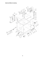
Page 32: ...32 Stand and Motor Assembly ...

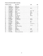
Page 33: ... 1490081 Hex Cap Screw M8x45 4 15 JWP15H 418 Power Cable 1 16 PAG M02 Motor Cable 1 17 PG M02 Jet Plaque 1 18 TS 2245081 Flat Head Screw M5x8 2 19 TS 2286201 Flat Head Screw M6x20 4 20 PJH S02 Door 1 21 TS 1540071 Hex Nut M10 1 22 TS 1550071 Flat Washer M10 1 23 PJN S02 Foot Brake 1 24 TS 0060111 Hex Cap Screw 3 8 16x2 1 2 4 25 PG M05 Wheel 4 26 TS 0561031 Hex Nut 3 8 16 4 27 5MA L05 Strain Relief...

Page 34: ...34 Electrical Connections ...

Page 35: ...35 ...

Page 36: ...36 WMH Tool Group 2420 Vantage Drive Elgin Illinois 60124 Phone 800 274 6848 www wmhtoolgroup com ...

Reviews: