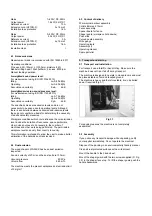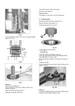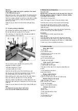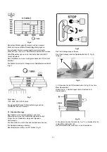
Fig 13
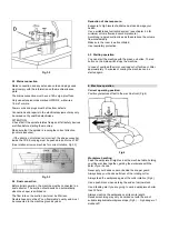
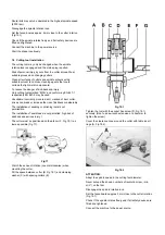
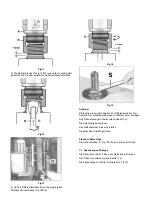
4) Firmly tighten the arbour nut (N, Fig 14) using the supplied
spanner (S, Fig 15).
Fig 14
Fig 15
Attention:
Verify correct nut placement.
The nut must have minimum 3mm distance to the end of
spindle nose thread.
Install the cutting tool (see chapter 7.4):
Disengage the spindle rotation lock.
Connect the machine to the power source.
Start the shaper cautiously.
Arbour removal:
The draw bar (D, Fig 12&13) must be removed first.
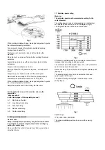
7.3 Collet installation
Disconnect the machine from the power source.
Remove the arbour (see chapter 7.2)
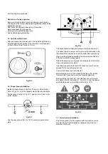
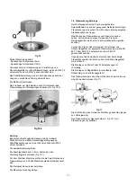
Install the collet with nut (Q, Fig 16.1).
Fig 16.1
Collets supplied with the machine:
- Collet Ø 8 mm
- Collet Ø 12 mm.
To reduce the danger of kick-back and injury.
Only cutting tools marked “MAN” and conforming EN 847-1
respectively EN 847-2 may be used.
Router bits must be clamped on a shaft length of minimum
20mm.
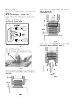
Tighten the nut (Q).
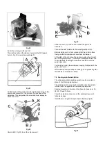
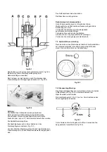
Cover the clearance zone around the cutter with table insert
rings (A, Fig 16.2).
Fig 16.2
Attention:
At the lower spindle speeds and at smaller tool diameters an
increased risk of workpiece kickback exists.
Summary of Contents for JWS-34KX
Page 44: ...A 1 A 2 A 3 A 4 A 5 ...

