background image


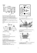
Router bits may only be operated in the highest spindle speed 
(8000 rpm). 

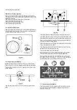
Disengage the spindle rotation lock. 

Set the fence boards approx. 5mm close to the cutter rotation 
(Fig 19.1). 

Check if the spindle rotates freely and if all safety devices are 
fitted and tightened. 

Connect the machine to the power source. 

Start the shaper cautiously. 


7.4  Cutting tool installation 

The cutting tool may only be changed when the spindle 
rotation lock is engaged and the mains plug is pulled. 

Risk of personal injury by cuts from the cutter knives. Wear 
suitable gloves when changing cutters. 

Clean all surfaces of cutters and spindle arbours with a 
suitable solvent (do not use cleaning agents that could 
corrode the light metal components). 

To reduce the danger of kick-back and injury. 
Only cutting tools marked “MAN” and conforming EN 847-1 
respectively EN 847-2 may be used. 

Unsuitable, incorrectly mounted, dull, cracked of bent cutter 
knives can break or increase the risk of kickback considerably. 

The installation of sanding or polishing tools is not 
permissible. 

The installation of saw blades is not permitted, high risk of 
kickback and serious injury ! 

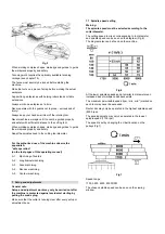
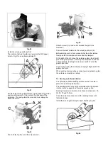
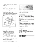
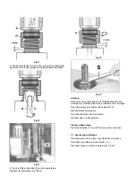
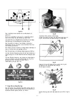
The cutter must be positioned on the arbour (F, Fig 18.1) as 
low as possible (Fig 17). 


Fig 17 

Watch the sense of rotation (counter clockwise) when 
mounting the cutter. 

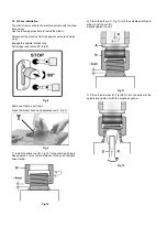
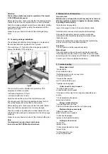
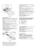
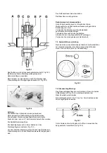
Fill the space between cutter (B, Fig 18.1) and clamping 
washer (C) with spacing collars (E). 


Fig 18.1 

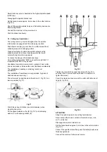
Tighten the tool with the socket hex screw (D, Fig 18.1) 
securely. (Don’t use a wrench extension or a hammer to 
tighten the screw) 

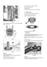
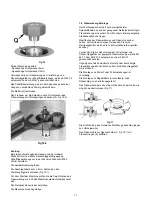
Cover the clearance zone around the cutter with table insert 
rings (A, Fig 18.2). 


Fig 18.2


ATTENTION: 

Adapt the spindle speed to the cutting tool diameter. 

Never exceed the shown numbers of revolution (rpm, /min, 
min

-1

) on the tool. 

Disengage the spindle rotation lock. 

Set the fence boards approx. 5mm close to the cutter rotation 
(Fig 19.1). 

Check if the spindle rotates freely and if all safety devices are 
fitted and tightened. 

Connect the machine to the power source. 

Summary of Contents for JWS-34KX

Page 1: ...Single Spindle Moulder Original GB Operating Instructions Translations D Gebrauchsanleitung F Mode d emploi TOOL FRANCE S A S 9 Rue des Pyrénées F 91090 LISSES France www promac fr M 708502KXM 708502KXT 2021 05 ...

Page 2: ...etic compatibility elektromagnetische Verträglichkeit compatibilité électromagnétique designed in consideration of the standards und entsprechend folgender zusätzlicher Normen entwickelt wurde et été développé dans le respect des normes complémentaires suivantes EN ISO 19085 1 2017 EN ISO 19085 6 2017 EC type examination performed by EG Baumusterprüfung durchgeführt von examen CE de type par DGUV ...

Page 3: ...s with the regulations UK SI 2008 No 1597 and amendments the Supply of Machinery Safety Regulations 2008 UK SI 2016 No 1091 and amendments the Electromagnetic Compatibility Regulations 2016 designed in consideration of the standards BS EN ISO 19085 1 2017 BS EN ISO 19085 6 2017 Responsible for the Documentation TOOL FRANCE SAS 2021 05 10 Christophe SAINT SULPICE General Manager TOOL FRANCE SAS 9 R...

Page 4: ...aterial defects and manufacturing faults This warranty does not cover any defects which are caused either directly or indirectly by incorrect use carelessness accidental damage repair or inadequate maintenance or cleaning as well as normal wear and tear Further details on warranty e g warranty period can be found in the General Terms and Conditions GTC that are integral part of the contract These ...

Page 5: ...an change your behaviour Keep children and visitors a safe distance from the work area Do not remove chips and workpiece parts until the machine is at a complete standstill Never leave a running machine unattended Before you leave the workplace switch off the machine Do not operate the electric tool near inflammable liquids or gases Observe the fire fighting and fire alert options for example the ...

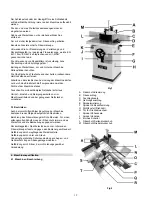
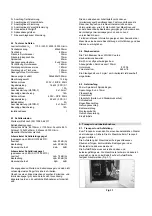
Page 6: ...itable dust exhaust system The use of incorrect mains supply or a damaged power cord can lead to injuries caused by electricity 4 Machine specifications 4 1 Machine description Fig 1 A Shaper guard lock B Shaper fence C Fence boards D Mitre gauge E Spindle rotation lock F Spindle up down lock G Speed select viewing window H Motor pulley access door I Spindle up down scale J Spindle up down handwhe...

Page 7: ...lace levels can vary from country to country This information is intended to allow the user to make a better estimation of the hazards and risks involved 4 4 Dust emission The wood shaper JWS 34KX has been dust emission inspected At an air velocity of 20 m s on the dust port dia 100mm Vacuum pressure 800 Pa Volume flow 565 m h The machine meets the present workplace dust emission limit of 2 mg m 4...

Page 8: ...tion of dust exposure Exposure to high levels of airborne dust can damage your health Use a suitable dust extraction system see chapter 4 4 for minimum volume flow and vacuum pressure Avoid long angled suction lines as these reduce the volume flow considerably Make sure the room is well ventilated Use respiratory protection 5 5 Starting operation You can start the machine with the green on button ...

Page 9: ...ining of boards A 2 Longitudinal machining A 3 Face machining A 4 Recess machining A 5 Contour machining 7 Setup and adjustments General note Setup and adjustment work may only be carried out after the machine is protected against accidental starting by pulling the mains plug Make sure that the cutter is running clear after every setup or adjustment done 7 1 Spindle speed setting Warning The spind...

Page 10: ...rotate 90 Fig 8 Fig 8 Remove all table insert rings Clean the arbour shank and spindle bore T Fig 9 Fig 9 1 Install the arbour nut N Fig 10 to the machine spindle Keep approx 2 turns 4mm distance to the end of spindle nose thread Fig 10 2 Place the arbour A Fig 11 into the spindle and thread arbour onto the nut N Slightly tighten the nut Fig 11 3 Place the draw bar D Fig 12 13 into the bottom of t...

Page 11: ...ollet installation Disconnect the machine from the power source Remove the arbour see chapter 7 2 Install the collet with nut Q Fig 16 1 Fig 16 1 Collets supplied with the machine Collet Ø 8 mm Collet Ø 12 mm To reduce the danger of kick back and injury Only cutting tools marked MAN and conforming EN 847 1 respectively EN 847 2 may be used Router bits must be clamped on a shaft length of minimum 2...

Page 12: ... dull cracked of bent cutter knives can break or increase the risk of kickback considerably The installation of sanding or polishing tools is not permissible The installation of saw blades is not permitted high risk of kickback and serious injury The cutter must be positioned on the arbour F Fig 18 1 as low as possible Fig 17 Fig 17 Watch the sense of rotation counter clockwise when mounting the c...

Page 13: ... Fig 19 2 to securely guide small gibs Fig 19 2 The spacer board is clampled between the fence boards C The spacer board is a wear part and a new board needs to be fabricated if the clearance around the cutter becomes too big Have a scrap workpiece available to allow proper positioning of the fence and the shaper guard Adjust the shaper guard to guide the workpiece and to protect from accidental c...

Page 14: ...ed At the start of the cut move the workpiece along the straight part of the guide plate F This way the workpiece enters the cutter gradually reaching the maximum depth of cut at the guide plate mark Continue by moving the workpiece keeping it aligned with the guide plate mark When working complex shapes make jigs and guides to guide the workpiece properly and safely 7 8 Sanding spindle installati...

Page 15: ...General notes Maintenance and inspection work may only be carried out after the machine is protected against accidental starting by pulling the mains plug Clean the machine regularly Inspect the proper function of the dust extraction daily Defective safety devices must be replaced immediately All protective and safety devices must be re attached immediately after completed cleaning maintenance and...

Page 16: ... materials which can be recovered or recycled Please leave it at a specialized institution This symbol indicates separate collection for electrical and electronic equipment required under the WEEE Directive Directive 2012 19 EC and is effective only within the European Union 11 Available accessories Stock number 10000251 30mm spindle arbour incl spacing collars Stock number 10000252 Sanding spindl...

Page 17: ...e TOOL FRANCE SAS garantiert dass das die von ihr gelieferte n Produkt e frei von Material und Herstellungsfehlern ist sind Diese Garantie deckt keinerlei Mängel Schäden und Fehler ab die direkt oder indirekt durch falsche oder nicht sachgemäße Verwendung Fahrlässigkeit Unfallschäden Reparaturen oder unzureichende Wartungs oder Reinigungsarbeiten sowie durch natürliche Abnutzung im Gebrauch verurs...

Page 18: ...chten Sie dass die elektrische Zuleitung nicht den Arbeitsablauf behindert und nicht zur Stolperstelle wird Den Arbeitsplatz frei von behindernden Werkstücken etc halten Seien Sie aufmerksam und konzentriert Gehen Sie mit Vernunft an die Arbeit Achten Sie auf ergonomische Körperhaltung Sorgen Sie für sicheren Stand und halten Sie jederzeit das Gleichgewicht Arbeiten Sie niemals unter dem Einfluss ...

Page 19: ...beschädigtes Netzkabel sofort aus Umrüst Einstell und Reinigungsarbeiten nur im Maschinenstillstand und bei gezogenem Netzstecker vornehmen 3 3 Restrisiken Auch bei vorschriftsmäßiger Benutzung der Maschine bestehen die nachfolgend aufgeführten Restrisiken Berührung des Fräswerkzeugs im Schnittbereich Für einen wirkungsvollen Schutz muss der Frässchutz immer an das Werkstück und die Bearbeitung an...

Page 20: ...hl es einen Zusammenhang zwischen Emissions und Immissionspegel gibt kann daraus nicht zuverlässig abgeleitet werden ob zusätzliche Maßnahmen erforderlich sind Die den aktuellen am Arbeitsplatz vorhandenen Immissionspegel beeinflussenden Faktoren umfassen die Dauer der Exposition die Raumcharakteristik andere Lärmquellen usw wie z B die Anzahl der Maschinen und andere benachbarte Bearbeitungsvorgä...

Page 21: ...nrichtungen Auf korrekte Drehrichtung der Frässpindel achten gegen den Uhrzeigersinn siehe Schaubild an der Maschine Fig 3 3 Fig 3 3 Bei falscher Drehrichtung ist der Phasenwender des CEE Steckers gedrückt um 180 zu drehen 5 4 Absaug Anschluss Die Maschine muss vor der Inbetriebnahme an eine Absaugung angeschlossen werden und zwar derart dass sich beim Einschalten der Maschine die Absaugung selbst...

Page 22: ...beiten Sie immer nur ein Werkstück zugleich Die Maschine niemals mit abgebauten Schutzeinrichtungen betreiben Hohe Verletzungsgefahr Halten Sie immer ausreichend Abstand zum Fräswerkzeug Bearbeiten Sie kein Werkstück welches nicht sicher mit einem ausreichenden Sicherheitsabstand zum Fräswerkzeug geführt werden kann Bei komplizierten Formen Schablonen zum exakten und sicheren Führen herstellen Pas...

Page 23: ... Sichtfenster überprüft werden 7 2 Fräsdorn Montage Der Fräsdorn ist mit einer Zugstange und einer Differentialmutter auf der Maschinenspindel befestigt Folgen Sie zur Fräsdornmontage den folgenden Anweisungen Die Stromzufuhr durch Ziehen des Netzsteckers trennen Die Spindelarretierung einrasten Dazu Rastbolzen ziehen und 90 drehen Fig 8 Fig 8 Die Tisch Einlegeringe entfernen Den Fräsdornkegel und...

Page 24: ... Position der Differentialmutter Der Abstand zum Gewindeende muss mindestens 3mm betragen Das Fräswerkzeug montieren siehe Kapitel 7 4 Die Spindelarretierung lösen Den Netzanschluss wieder herstellen Die Maschine vorsichtig starten Fräsdorn Demontage Die Dehnschraube D Fig 12 13 ist zuerst zu entfernen 7 3 Spannzangen Montage Die Stromzufuhr durch Ziehen des Netzsteckers trennen Den Fräsdorn entfe...

Page 25: ...s wieder herstellen Die Maschine vorsichtig starten 7 4 Fräswerkzeug Montage Der Werkzeugwechsel darf nur bei eingerasteter Spindelblockierung und bei gezogenem Netzstecker erfolgen Fräswerkzeuge sind scharf Zum Wechseln immer geeignete Arbeitshandschuhe tragen Oberflächen der Fräswerkzeuge und Fräsdorne sauber halten mit Harzlöser reinigen verwenden Sie keine Reinigungsmittel welche die Leichtmet...

Page 26: ...len Die Maschine vorsichtig starten Reduzierung der Lärmexposition Hohe Lärmexposition kann zu Hörschäden führen Werkzeugform und Drehzahl beeinflussen maßgeblich die Entstehung von Lärm Verwenden Sie Werkzeuge mit weitestgehend geschlossenem Rotationskörper Vermeiden Sie unnötig hohe Drehzahlen Arbeiten Sie nur mit gut geschärften Werkzeugen Verwenden Sie einen geeigneten Gehörschutz 7 5 Spindel ...

Page 27: ...fen Sie die freie Rotation des Fräswerkzeugs und ob alle Maschinenelemente festgespannt sind Vor dem Start der Maschine den Deckel des Fräsgehäuses nach vorn schieben und mit 2 Griffschrauben T Fig 19 2 festklemmen Den Frässchutz Druckschuhe in Arbeitsstellung bringen Fig 19 3 Fig 19 3 7 7 Bogenfräsanschlag Montage Der mit der Maschine gelieferte Bogenfräsanschlag Fig 20 kann am Maschinentisch bef...

Page 28: ... Es können Schleifhülsen mit Durchmesser 25 38 50 75 und 100mm verwendet werden Den Freiraum um den Schleifdorn je nach Durchmesser der Schleifhülse mit Tisch Einlegeringen abdecken Montieren Sie den Bogenfräsanschlag zur Staubabsaugung Fig 24 Fig 24 Achtung Der Schleifdorn darf nur in der niedrigsten Drehzahl 1700 U min betrieben werden Vor dem Start der Maschine prüfen sie die freie Rotation des...

Page 29: ...otor startet nicht Kein Strom Zuleitung und Sicherung prüfen Motor Schalter oder Kabel defekt Elektrofachkraft kontaktieren Überlastschutz hat reagiert Abkühlen lassen und erneut starten Spindelindexierung ist eingerastet Drehzahl kommt nicht hoch Werkzeug zu groß oder zu schwer niedere Drehzahlstufe wählen Zuleitung zu lang oder zu schwach Stromversorgung verbessern Riemenspannung zu hoch Riemens...

Page 30: ...leifhülsen in unterschiedlicher Körnung siehe die JET Preisliste JVOS 10 und JOSS 10 Artikel Nummer 10000253 Zapfenschneid Schlitten Artikel Nummer 709207 Rollenbock klappbar 12 Sicheres Arbeiten Siehe Anhang A auf den letzten Seiten der Bedienungsanleitung A 1 Fräsen von Platten A 2 Fräsen von Längsseiten A 3 Fräsen von Querseiten A 4 Einsetzfräsen A 5 Fräsen von Konturen ...

Page 31: ... s fourni s est sont exempt s de défauts matériels et de défauts de fabrication Cette garantie ne couvre pas les défauts qui sont causés directement ou indirectement par l utilisation incorrecte la négligence les dommages accidentels la réparation la maintenance ou le nettoyage incorrects et l usure normale Les détails sur la garantie période de garantie par exemple peuvent être trouvés dans les c...

Page 32: ...gues d alcool ou de médicaments Eloigner de la machine toutes personnes incompétentes surtout les enfants Ne pas enlever les copeaux et les pièces usinées avant que la machine ne soit à l arrêt Ne jamais laisser la machine en marche sans surveillance Arrêter la machine avant de quitter la zone de travail Ne pas mettre la machine à proximité de liquides ou de gaz inflammables respecter les consigne...

Page 33: ...ières de bois copeaux et bruit Porter des équipements de sécurité personnels tels que lunettes cache visage pour travailler à la machine Utiliser un collecteur de poussières Danger par câble électrique endommagé usé ou mal branché 4 Spécifications 4 1 Description de la machine Fig1 A Serrage presseurs B Guide de toupie C Plaque de butée D Guide d onglet E Verrou d arbre blocage F Serrage élévation...

Page 34: ...ur peut estimer les dangers et les risques possibles 4 4 Emission de poussière L émission de poussière de la toupie JWS 34KX a été évaluée A une vitesse d air de 20 m s à la buse d aspiration d un diamètre 100mm Pression diminuée 800 Pa Volume 565 m h Ainsi le paramètre de concentration toléré de 2 mg m est assuré 4 5 Contenu de la livraison Arbre 30mm avec anneaux Pinces de serrage 8 et 12mm Guid...

Page 35: ...tion de la qualité difficilement inflammable et intégrer les tuyaux dans la mise à la terre de la machine Réduction de l exposition à la poussière L exposition à des niveaux élevés de poussière atmosphérique peut nuire à votre santé Utilisez un système d extraction adapté voir chapitre 4 4 pour le débit volumique minimum et la pression négative Évitez les conduites d aspiration longues angulaire c...

Page 36: ...ère page de ce mode d emploi A 1 Toupillage de panneaux A 2 Toupillage longitudinal A 3 Toupillage transversal A 4 Reprise de travail A 5 Toupillage de contours 7 Réglages Attention Faire tous les travaux de maintenance ou de réglage après avoir débranché la machine du réseau Vérifier la rotation de l outil après chaque travail de maintenance ou de réglage 7 1 Réglage de la vitesse Attention La vi...

Page 37: ...er à 90 Fig 8 Fig 8 Enlever les anneaux de la table Nettoyer le cône du mandrin et le porte arbre T Fig 9 Fig 9 1 Visser l écrou différentiel N Fig 10 sur la broche de la machine Ménager un espace d environ 2 tours 4mm jusqu au bout du filetage Fig 10 2 Monter le mandrin de fraisage A Fig 11 le visser dans l écrou différentiel N Il faut tout d abord ne visser l écrou différentiel que légèrement Fi...

Page 38: ... premier 7 3 Montage des pinces de serrage Déconnecter la machine du réseau Enlever le mandrin voir chapitre 7 2 Fixer la pince de serrage avec l écrou Q Fig 16 Fig 16 Sont livrés avec la machine Pince de serrage diamètre 8mm Pince de serrage diamètre 12 mm Afin de réduire les risques de blessures et de contrecoups n utiliser que des fraises à queue appropriées qui correspondent aux normes EN 847 ...

Page 39: ...47 2 et qui portent la mention MAN Des outils mal montés usés ou endommagés peuvent casser et augmentent le danger de contrecoup Le montage d outils d affilage ou de polissoirs est interdit Le montage de lames de scie est interdit risque élevé de rebond et de blessures Installer l outil de toupillage sur l arbre aussi bas que possible Fig 17 Fig 17 Vérifier la direction de rotation de l outil mont...

Page 40: ... continuité pour le guidage sûr d une latte étroite A Fig 19 2 Fig 19 2 Serrer la plaque de continuité entre les butées à onglet C La plaque de continuité est une pièce soumise à l usure et doit être remplacée aussitôt que l espace autour de l outil devient trop grand Si possible utiliser un reste de bois pour le positionnement et le réglage du guide de toupie Installer le dispositif de protection...

Page 41: ...le long de la barre conductrice F Ainsi la pièce glisse doucement dans le rayon d action de l outil L enlèvement maximal des copeaux est atteint à la flèche de repérage Continuer de guider la pièce à la flèche de repérage Ainsi un enlèvement des copeaux constant vous est garanti Pour des formes compliquées créer un patron pour un travail exact et sûr 7 8 Montage broche ponceuse La broche ponceuse ...

Page 42: ...en direction de l outil Pour cela appuyer la pièce d oeuvre avec les deux mains contre la butée de guidage E Garder toujours suffisamment de distance à l outil de toupillage Indication Le travail de tenonnage demande de la puissance et du couple Une vitesse de 3500 T min donne en général les meilleurs résultats 8 Entretien et inspection Attention Faire tous les travaux de maintenance réglage ou ne...

Page 43: ... hauteur difficile Graissage insuffisant Graisser les broches de précision de l arbre Arrêt d arbre bloqué Résultat de travail insuffisant La courroie glisse Resserrer ou remplacer la courroie Résidu de résine sur la table Nettoyer et mettre de la cire 10 Protection de l environnement Protégez l environnement Votre appareil comprend plusieurs matières premières différentes et recyclables Pour élim...

Page 44: ...A 1 A 2 A 3 A 4 A 5 ...

Reviews: