background image


13

10.0

  Load Limits 

10.1

  Load Chain  

Capacity 

5 Links 
Normal 

5 Links 

Limit 

0.25 ton 

2.36” 

2.43" 

0.5 ton 

2.95” 

3.04" 

1 ton 

3.74” 

3.85" 

1.5 ton 

4.13” 

4.25" 

2 ton 

4.72” 

4.86" 

3 ton 

4.13” 

4.25" 

5 ton 

5.31” 

5.47" 

10 ton 

5.31” 

5.47" 

15 ton 

5.31” 

5.47" 

20 ton 

5.31” 

5.47" 


Table 1 

Carefully inspect the entire load chain. As 
illustrated in Figure 15, measure five consecutive 
links with callipers to measure the length.  Check 
every three feet and especially where excessive 
wear is indicated. Any load chain that shows 
noticeable deformation or heat influence must be 
replaced with a new one. Never extend load chain 
by welding a second piece to the original. 


10.2

  Hooks (Top & Bottom) 


Capacity 

“A”  

Norm 

“A”  

Limit 

“B”  

Norm

“B” 

Limit 

0.25 ton 

1.39” 

1.47” 

-- 

-- 

0.5 ton 

1.36" 

1.44" 

-- 

-- 

1 ton 

1.77" 

1.88" 

-- 

-- 

1.5 ton 

1.86" 

1.97" 

-- 

-- 

2 ton 

2.05" 

2.17" 

-- 

-- 

3 ton 

2.45" 

2.60" 

-- 

-- 

5 ton 

3.06" 

3.24" 

-- 

-- 

10 ton 

-- 

-- 

2.52" 

2.67" 

15 ton 

-- 

-- 

3.15” 

3.34” 

20 ton 

-- 

-- 

3.23” 

3.42” 


Table 2 

See Figure 16. Replace the hook when the “A” 
measurement is wider than “A” Limit in the table 
above. Never heat-treat the hook or attach anything 
to the hook by welding.


Figure 15 


A

B


Figure 16 


Summary of Contents for L100-25

Page 1: ...New Sanford Road LaVergne Tennessee 37086 Part No M 106210 Ph 800 274 6848 Revision D1 07 2018 www jettools com Copyright 2018 JET 1 ton model shown For L100 200 serial no 15070001 and higher For L100...

Page 2: ...st must have the same capacity as the load to be moved 15 Never allow the load chain to set over sharp edges All lifts must be made with straight chain that is free of obstacles 16 If the hand chain i...

Page 3: ...on 10 7 5 Chain Installation 0 5 to 2 Ton Hoists 10 7 6 Chain Installation 3 to 5 Ton Hoists 10 7 7 Chain Installation 10 to 20 Ton Hoists 11 8 0 Overload Protection 11 9 0 Inspection and Maintenance...

Page 4: ...ing procedures maintenance instructions and parts breakdown This hoist has been designed and constructed to provide consistent long term operation if used in accordance with instructions set forth in...

Page 5: ...5 4 0 Specifications...

Page 6: ...d with your JET chain hoist is designed manufactured and tested for proper fit and durability Over a period of time the chain may need to be replaced For your own safety use factory replacement chain...

Page 7: ...equal to the total load to be lifted 5 Check that the chain is not twisted at the bottom hook All welds should face the same direction Figure 4 6 For hoists with two or more falls of chain make sure...

Page 8: ...vise jaw Figure 7 4 Tighten the vise jaw 5 Using an adjustable wrench twist the link horizontally from front to back Figure 8 Open just far enough to insert or remove a second chain link Note Chain l...

Page 9: ...of the increase in length 4 If the length of used chain exceeds 2 1 2 percent of the unused chain replace the chain See Load Limits on page 13 for specific link measurements Do not add to the load cha...

Page 10: ...ghten 7 6 Chain Installation 3 to 5 Ton Hoists Referring to Figure 13 1 After installing the load chain into the load chain sprocket B run the remaining chain through your hand to remove any twist The...

Page 11: ...F Check that the load chain is not twisted and welds face away from the pulley 6 Remove the cotter pin and chain anchor pin in the upper hook slot G 7 Insert the last link into the upper hook slot 8...

Page 12: ...se serious injury 1 Clean hoist after each use and oil lightly NOTE Do not get oil on brake system 2 Do not drop or drag the hoist 3 Store the hoist in a clean and dry environment 4 While not mandator...

Page 13: ...where excessive wear is indicated Any load chain that shows noticeable deformation or heat influence must be replaced with a new one Never extend load chain by welding a second piece to the original...

Page 14: ...Replace load sheave if damaged or excessively worn Ratchet disc teeth pawls or pawl springs worn or damaged Inspect elements and replace if needed Bearing failure Contact JET service center for disas...

Page 15: ...are listed on the following pages To order parts or reach our service department call 1 800 274 6848 Monday through Friday see our website for business hours www jettools com Having the Model Number...

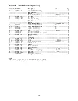
Page 16: ...16 13 1 1 L 100 Chain Hoist Parts Breakdown...

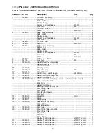
Page 17: ...Wheel Cover 1 Hand Chain Guide 2 8A L100 25 8A Warning Label 1 9 L100 25 9 1 Wheel Stopper M6 1 10 L100 25 10 1 Wheel Washer 1 12 L100 25 12 Hand Chain specify length 3x15 mm 1 13 L100 25 13 Hand Cha...

Page 18: ...Lock Nut Black Oxide M6 3 28 L100 25 28 Rivet 2x4 mm 4 29 LM000013 Name Plate L100 25 1 29 LM000014 Name Plate L100 25 with overload 1 30 L100 25 30 Spur Gear Assembly 2 Spur Gear 2 Pinion Gear 2 31...

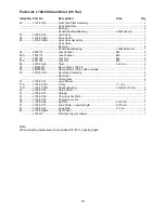
Page 19: ...and Chain Guide 2 8A L100 50 8A Warning Label 1 9 L100 25 9 1 Wheel Stopper M6 1 10 L100 25 10 1 Wheel Washer 1 12 L100 50 12 Hand Chain specify length 4 8x22 mm 1 13 L100 50 13 Hand Chain Connecting...

Page 20: ...8 3 28 L100 50 28 Rivet 3x5 mm 4 29 LM000015 Name Plate L100 50 1 29 LM000016 Name Plate L100 50 with overload 1 30 L100 50 30 Spur Gear Assembly 2 Spur Gear 2 Pinion Gear 2 31 L100 50 31 Load Sheave...

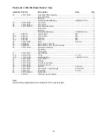
Page 21: ...Chain Guide 2 8A L100 50 8A Warning Label 1 9 L100 100 9 1 Wheel Stopper M8 1 10 L100 100 10 1 Wheel Washer 1 12 L100 100 12 Hand Chain specify length 5x25 mm 1 13 L100 100 13 Hand Chain Connecting Li...

Page 22: ...8 L100 100 28 Rivet 3x6 mm 4 29 LM000017 Name Plate L100 100 1 29 LM000018 Name Plate L100 100 with overload 1 30 L100 100 30 Spur Gear Assembly 2 Spur Gear 2 Pinion Gear 2 31 L100 100 31 Load Sheave...

Page 23: ...d Chain Guide 2 8A L100 50 8A Warning Label 1 9 L100 100 9 1 Wheel Stopper M8 1 10 L100 100 10 1 Wheel Washer 1 12 L100 100 12 Hand Chain specify length 5x25 mm 1 13 L100 100 13 Hand Chain Connecting...

Page 24: ...28 L100 100 28 Rivet 3x6 mm 4 29 LM000019 Name Plate L100 150 1 29 LM000020 Name Plate L100 150 with overload 1 30 L100 300 30 Spur Gear Assembly 2 Spur Gear 2 Pinion Gear 2 31 L100 300 31 Load Sheave...

Page 25: ...Chain Guide 2 8A L100 50 8A Warning Label 1 9 L100 100 9 1 Wheel Stopper M8 1 10 L100 100 10 1 Wheel Washer 1 12 L100 100 12 Hand Chain specify length 5x25 mm 1 13 L100 100 13 Hand Chain Connecting Li...

Page 26: ...28 L100 100 28 Rivet 3x6 mm 4 29 LM000021 Name Plate L100 200 1 29 LM000022 Name Plate L100 200 with overload 1 30 L100 200 30 Spur Gear Assembly 2 Spur Gear 2 Pinion Gear 2 31 L100 200 31 Load Sheave...

Page 27: ...M12 2 Lock Washer M12 2 Bottom Hook Holder 1 8 L100 300 8G Hand Wheel Cover Assembly 1 Hand Wheel Cover 1 Hand Chain Guide 2 8A L100 50 8A Warning Label 1 9 L100 100 9 1 Wheel Stopper M8 1 10 L100 100...

Page 28: ...L100 100 28 Rivet 3x6 mm 4 29 LM000023 Name Plate L100 300 1 29 LM000024 Name Plate L100 300 with overload 1 30 L100 300 30 Spur Gear Assembly 2 Spur Gear 2 Pinion Gear 2 31 L100 300 31 Load Sheave 1...

Page 29: ...ttom Hook Holder 1 8 L100 500 8G Hand Wheel Cover Assembly 1 Hand Wheel Cover 1 Hand Chain Guide 2 8A L100 50 8A Warning Label 1 9 L100 100 9 1 Wheel Stopper M8 1 10 L100 100 10 1 Wheel Washer 1 12 L1...

Page 30: ...LM000025 Name Plate L100 500 1 29 LM000026 Name Plate L100 500 with overload 1 30 L100 500 30 Spur Gear Assembly 2 Spur Gear 2 Pinion Gear 2 31 L100 500 31 Load Sheave 1 31A L100 500 31A C Clip 24 mm...

Page 31: ...ring 1 Socket Head Cap Screw M5x30 1 Lock Nut M5 1 Idle Shaft 2 Idle Sheave 2 Needle Bearing 1 Socket Head Cap Screw M12x45 3 Lock Nut M12 3 Lock Washer M12 3 Hook Collar Bushing 1 Bottom Hook Holder...

Page 32: ...27A F001754 Lock Nut M8 3 28 L100 100 28 Rivet 3x6 mm 4 29 LM000027 Name Plate L100 1000 1 29 LM000028 Name Plate L100 1000 with overload 1 30 L100 500 30 Spur Gear Assembly 2 Spur Gear 2 Pinion Gear...

Page 33: ...le Spring 1 Socket Head Cap Screw M6x30 1 Lock Nut M6 1 Idle Shaft 1 Idle Sheave 3 Needle Bearing 3 Socket Head Cap Screw 3 Lock Nut 3 Lock Washer 3 Hook Collar Bushing 1 Bottom Hook Holder 1 8 L100 5...

Page 34: ...L100 100 28 Rivet 3x6 mm 4 29 LM000029 Name Plate L100 1500 1 29 LM000030 Name Plate L100 1500 with overload 1 30 L100 500 30 Spur Gear Assembly 2 Spur Gear 2 Pinion Gear 2 31 L100 500 31 Load Sheave...

Page 35: ...t Head Cap Screw M6x30 1 Lock Nut M6 1 Needle Bearing 4x20 mm 1 Idle Shaft 4 Idle Sheave 2 Bottom Hook Shaft 1 Snap Ring 35 mm 4 Snap Ring 42 mm 2 Hook Collar Bushing 1 Bottom Hook Holder 1 8 L100 500...

Page 36: ...6 27 F001756 Lock Nut M12 6 27A F001754 Lock Nut M8 6 28 L100 100 28 Rivet 3x6 mm 8 29 LM000031 Name Plate L100 2000 2 29 LM000032 Name Plate L100 2000 with overload 2 30 L100 500 30 Spur Gear Assemb...

Page 37: ...tional action needed JET has Authorized Service Centers located throughout the United States For the name of an Authorized Service Center in your area call 1 800 274 6846 or use the Service Center Loc...

Page 38: ...38 This page intentionally left blank...

Page 39: ...39 This page intentionally left blank...

Page 40: ...40 427 New Sanford Road LaVergne Tennessee 37086 Phone 800 274 6848 www jettools com...

Reviews: