background image


7

Unpacking 

Upon delivery, open shipping containers and check 
that all parts are in good condition. Any damage 
should be reported to your distributor and shipping 
agent immediately. Before proceeding further, read 
your manual and familiarize yourself thoroughly 
with assembly, maintenance and safety 
procedures. 

Compare the contents of your container with the 
following parts list to make sure all parts are intact. 
Missing parts, if any, should be reported to your 
distributor. Read the instruction manual thoroughly 
for assembly, maintenance and safety instructions. 

Shipping Contents 

0

1   Front Panel with Door (Stand) 

0

1   Rear Panel (Stand) 

0

2   Side Panel (Stand) 

0

1  Shelf 

0

2   M5x10 Screw 

0

2  M5 Flat Washer 

0

2   M5 Lock Washer 

0

1   Extension Table Assembly 

0

1   Drum Guard & Dust Port 

0

1   Owner’s Manual 

0

1  Warranty Card 

0

1   Table and Motor Unit 

0

1   Back Stop Bracket 

0

1   Belt Tension Handle 

0

1   Belt Tracking Tool 

0

1   Miter Gauge Assembly 

0

1   Sanding Belt 


Cabinet Hardware 

0

1   Lock Knob (20mm Length) 

0

2   Lock Knob (12mm Length) 

0

1   Lock Knob (35mm Length) 

0

4   Cabinet Pads 

0

4   5/16” x 5/8” Screws 

22   5/16” Flat Washers 
12   5/16” Hex Nuts 

0

8   5/16” x 5/8” Hex Cap Bolts 

0

2   5/16” x 1-1/4” Hex Cap Bolts 

0

4   Larger O/D 5/16” Flat Washers 

10   5/16” Lock Washers 
 

Extension Table Hardware 

0

5   1/4" x 5/8” Hex Cap Bolts 

0

5  1/4" Flat Washers 

0

5   1/4” Lock Washers 

0

1  Bracket 

0

2   10-24x3/4 Socket Head Cap Screws 


Dust Chute Hardware 

0

3   Pan Head Screws 


Tools Needed for Assembly 

2  12mm Wrench or sockets 
1  10mm Wrench or sockets 
1  Flat Head Screw Driver 
1  Cross Point Screw Driver 


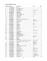
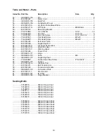
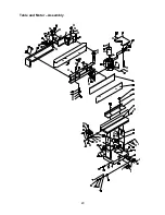
Summary of Contents for OES-80CS

Page 1: ...uctions and Parts Manual Oscillating Edge Sander Model OES 80CS WMH TOOL GROUP 2420 Vantage Drive Elgin Illinois 60124 Part No M 708447 Ph 800 274 6848 Revision B1 1 07 www wmhtoolgroup com Copyright...

Page 2: ...ostage prepaid to a location designated by us For the name of the location nearest you please call 1 800 274 6848 You must provide proof of initial purchase date and an explanation of the complaint mu...

Page 3: ...12 Changing the Sanding Belt 13 Belt Tracking Adjustment 13 Motor Mount Tracking Adjustment 14 Table Adjustment 14 Basic Operations 15 Horizontal Sanding 15 Vertical Sanding 15 Contour Sanding 16 Trou...

Page 4: ...ement and other masonry products Arsenic and chromium from chemically treated lumber Your risk of exposure varies depending on how often you do this type of work To reduce your exposure to these chemi...

Page 5: ...Maintain machinery with care Follow instructions for lubricating and changing accessories 27 Turn off the machine before cleaning Use a brush or compressed air to remove dust or debris do not use you...

Page 6: ...your local supplier or WMH Tool Group WMH Tool Group can also be reached at our web site www wmhtoolgroup com Specifications Stock Number 708447 Fence 4 H x 24 L Abrasive Belt Size 6 W x 89 L Dust Ch...

Page 7: ...f 02 M5x10 Screw 02 M5 Flat Washer 02 M5 Lock Washer 01 Extension Table Assembly 01 Drum Guard Dust Port 01 Owner s Manual 01 Warranty Card 01 Table and Motor Unit 01 Back Stop Bracket 01 Belt Tension...

Page 8: ...pan head screws two M5 flat washers and two M5 lock washers G 6 Finish the stand assembly by attaching the rear panel H to side panels C with four 5 16 x 5 8 hex cap screws eight 5 16 flat washers fo...

Page 9: ...re 5 1 From the rear of the sander remove the belt guard A by unscrewing two lock knobs B Take out the sanding belt and removable fence from behind the belt guard 2 Place the handle C on belt tensioni...

Page 10: ...the cover when closing in order to clear the motor case This is normal 4 Place washers G on two small lock knobs H and then insert the threaded end of one lock knob through the slot of the connection...

Page 11: ...ur Oscillating Edge Sander is ready to run at 115 volt operation This Oscillating Edge Sander when wired for 115 volt is intended for use on a circuit that has an outlet and a plug that looks like the...

Page 12: ...Lock Tension Adjustment 1 Disconnect the machine from the power source 2 Loosen unlock the handle B Fig 10 and place the platen in the horizontal position as shown in A Fig 10 Do not lock 3 Tension ec...

Page 13: ...h the belt by hand from left to right the direction indicated top of the platen and observe the belt s position on the rollers The oscillating movement of the belt is by design Observe the belt s rang...

Page 14: ...king hex nuts C that secure the tracking screws A 4 Turn one screw A a 1 4 turn and rotate the sanding belt by hand to observe which direction the adjustment is causing the belt to move If it is trave...

Page 15: ...by tightening the lock knobs G Fig 16 and Figure 17 The backstop H Fig 17 can also be used by swiveling the drum guard dust port J Fig 17 out of the way and placing the backstop pin in the positionin...

Page 16: ...m guard dust port E 2 Swing the end guard E back bringing the drive drum D into view 3 Tighten the lock knobs C 4 Mount the extension table A to the sander by inserting the post B into the bracket F 5...

Page 17: ...roken 1 Adjust stand so that it rests evenly on the floor 2 Tighten motor mount bolts 3 Replace spring Abrasive belt keeps tearing 1 Belt is running in the wrong direction 1 Arrow on the sanding belt...

Page 18: ...67021 Set Screw 1 4 20 1 4 1 27 EHVS80 27 Location Plate 1 28 EHVS80 28 Pointer 1 29 See Below Sanding Belt 6 W x 89 L 1 30 10104046 Miter Gauge Body 1 EHVS80 MG Miter Gauge Assembly 31 TS 081B042 Pan...

Page 19: ...Label 1 70 EHVS80 68 Power Cord 1 71 OES80CS 171 Hinge 2 72 OES80CS 172 Knob M6 2 73 OES80CS 173 Supporting Seat 1 74 TS 0206041 Socket Head Cap Screw 10 24x3 4 2 75 OES80CS 175 Spacer 2 76 EHVS80 34...

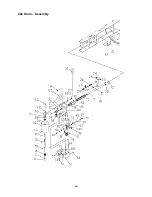
Page 20: ...20 Table and Motor Assembly...

Page 21: ...OES80CS 238 Gear Housing 1 39 TS 1502021 Socket Head Cap Screw M5x10 5 40 OES80CS 240 Bushing 2 41 OES80CS 241 Cam 1 42 OES80CS 242 Worm Gear 1 43 OES80CS 243 Worm Gear Shaft 1 44 OES80CS 244 Column...

Page 22: ...22 Idle Drum Assembly...

Page 23: ...crew 4 7 EHVS80CS S07 Rear Panel 1 8 TS 0561021 Hex Nut 5 16 18 4 9 TS 0051061 Hex Cap Screw 5 16 18x1 1 4 2 10 TS 1533032 Pan Head Screw M5x10 2 11 EHVS80CS S11 Door 1 12 EHVS80CS S12 Shelf 1 13 EHVS...

Page 24: ...24 Wiring Diagram...

Reviews: