background image


1.0

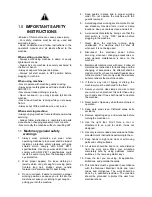
  IMPORTANT SAFETY 

INSTRUCTIONS 

- Misuse of this machine can cause serious injury. 
- For safety, machine must be set up, used and 
serviced properly. 
- Read, understand and follow instructions in the 
operator’s manual and all labels affixed to the 
machine. 


When setting up machine: 

- Always avoid using machine in damp or poorly 
lighted work areas. 
- Always be sure machine is securely anchored to 
the floor or bench. 
- Always keep machine guards in place. 
- Always put start switch in OFF position before 
plugging in machine.  


When using machine: 

- Never operate with machine guards missing. 
- Always wear safety glasses with side shields (See 
ANSI Z87.1) 
- Never wear loose clothing or jewelry. 
- Never overreach 

 you may slip and fall into the 

machine. 
- Never leave machine running while you are away 
from it. 
- Always shut off the machine when not in use.  


When servicing machine: 

- Always unplug machine from electrical power while 
servicing. 
- Always follow instructions in operators and parts 
manual when changing accessory tools or parts. 
- Never modify the machine without consulting JET. 

1.1

  Machinery general safety 

warnings 

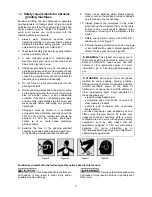
1. Always wear protective eye wear when 

operating machinery. Eye wear shall be impact 
resistant, protective safety glasses with side 
shields which comply with ANSI Z87.1 
specifications. Use of eye wear which does not 
comply with ANSI Z87.1 specifications could 
result in severe injury from the breakage of the 
eye protection. 

2.  Wear proper apparel. No loose clothing or 

jewelry which can get caught in moving parts. 
Contain long hair. Rubber soled, nonslip 
footwear is recommended for best footing. 

3.  Do not overreach. Failure to maintain a proper 

working position can cause you to fall into the 
machine or cause your clothing to get caught — 
pulling you into the machine.  

4.  Keep guards in place and in proper working 

order. Do not operate the machine with the 
guards removed. 

5.  Avoid dangerous working environments. Do not 

use stationary machine tools in wet or damp 
locations. Keep work areas clean and well lit. 

6.  Avoid accidental starts by being sure that the 

start switch is in the “OFF” position before 
plugging in the machine. 

7. Never leave the machine running while 

unattended. The machine shall be shut off 
whenever it is not being used. 

8. Disconnect the electrical power before 

servicing, whenever changing accessories or 
when general maintenance is done on the 
machine. 

9.  Maintain all machine tools with care.  Follow all 

maintenance instructions for lubricating and the 
changing of accessories. No attempt shall be 
made to modify or have makeshift repairs done 
to the machine. This not only voids the warranty 
but also renders the machine unsafe. 

10. If there is any risk of tipping or sliding, the 

machinery must be anchored to the floor. 

11.  Secure your work. Use clamps or a vise to hold 

your work, when practical. It is safer than using 
your hands and it frees both hands to operate 
the machine. 

12.  Never brush chips away while the machine is in 

operation. 

13. Keep work area clean. Cluttered areas invite 

accidents. 

14. Remove adjusting keys and wrenches before 

turning the machine on. 

15. Use the right tool. Don’t force a tool or 

attachment to do a job for which it was not 
designed. 

16.  Use only recommended accessories and follow 

manufacturer’s instructions pertaining to them. 

17. Keep hands in sight and clear of all moving 

parts and cutting surfaces. 

18. All visitors should be kept at a safe distance 

from the work area. Make your workshop 
completely safe by using padlocks, master 
switches, or by removing starter keys. 

19. Know the tool you are using; its application, 

limitations, and potential hazards. 

20.  This machine must be grounded in accordance 

with the National Electrical Code and local 
codes and ordinances. The work should be 
done by a qualified electrician. The machine 
should be grounded to protect the user from 
electrical shock. 

Summary of Contents for SWG Series

Page 1: ...Grinder Model SWG 272 SWG 272VS JET 427 New Sanford Road LaVergne Tennessee 37086 Part No M 577400 Ph 800 274 6848 Edition 1 11 2020 www jettools com Copyright 2020 JET Variable speed model Single sp...

Page 2: ...not operate the machine with the guards removed 5 Avoid dangerous working environments Do not use stationary machine tools in wet or damp locations Keep work areas clean and well lit 6 Avoid accidenta...

Page 3: ...er use an abrasive which shows backing nicks or cuts on the surface or edge or damage due to creasing or poor handling 10 Always present the workpiece to the wheel while resting the workpiece firmly o...

Page 4: ...tructed to provide consistent long term operation if used in accordan ce with the instructions set forth in this document This document is not however intended to be an exhaustive guide to grinding op...

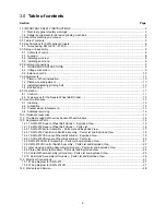
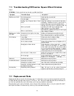
Page 5: ...13 9 4 Additional servicing 13 10 0 Optional accessories 13 11 0 Troubleshooting SWG series Square Wheel Grinders 14 12 0 Replacement Parts 14 12 1 1 SWG 272 Square Wheel Belt Grinder Exploded View 1...

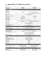
Page 6: ...ission 2 80 dB at 3ft without load Base Footprint L x W 35 7 16 x 16 15 16 in 900 x 430 mm Mounting hole dimensions Dia 7 16 in 11mm Belt Grinder Belt included L x W 50 grit 72 x 2 in 1829 x 50 8 mm B...

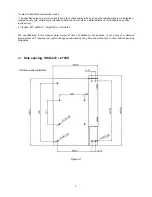
Page 7: ...e user to make a better estimation of the hazards and risks involved only L length W width H height Dia diameter The specifications in this manual were current at time of publication but because of ou...

Page 8: ...me are accessed behind the side panel to accept fasteners for this purpose Sect 4 1 shows the hole patterns An optional JET stand is available for this machine See sect 10 0 Use the 4 holes in front o...

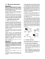
Page 9: ...t have 3 prong grounding plugs and 3 pole receptacles that accept the tool s plug Repair or replace damaged or worn cord immediately 2 Grounded cord connected tools intended for use on a supply circui...

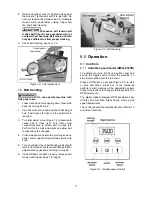
Page 10: ...er guard see Figure 7 2 Open side panel by turning its knob and lowering panel on its hinges 3 Loosen clamp handle on head casting See Figure 7 1 4 Install pivot shaft of platen or shaft of wheel all...

Page 11: ...l increments and allow belt to respond to the changes 4 Close side panel and secure by turning knob on panel Lower upper belt guard and secure with knob 5 Turn on grinder Check belt tracking belt shou...

Page 12: ...back in to stop machine green light will turn off To prevent accidental or unauthorized operation stop the machine and pull out the yellow safety key The key must be reinserted to start the machine P...

Page 13: ...nt Move switch to OFF to avoid personal injury If the contact wheel becomes worn a new contact wheel can be assembled to the existing wheel shaft and bearings refer to Figure 9 1 1 Lower tension lever...

Page 14: ...ed To adjust drive wheel loosen set screws and move drive wheel in or out on motor shaft as required To adjust contact wheel loosen shaft clamping screw and move contact wheel in or out as required La...

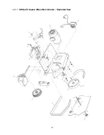
Page 15: ...15 12 1 1 SWG 272 Square Wheel Belt Grinder Exploded View...

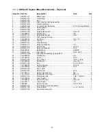
Page 16: ...16 x 1 1 19 SWG272 19 Nylon Flat Washer 5 16 3 20 BB 6200ZZ Ball Bearing 6200ZZ 2 21 SWG272 21 Idler Wheel OD3 x W2 1 SWG272 21E Idler Wheel Assembly include 20 1 22 TS 0680021 Flat Washer 1 4 1 23 T...

Page 17: ...sembly 4P 1 33 9 SWG272 339 Dust Cover 1 33 10 F001235 Phillips Pan Head Machine Screw 10 24 x 1 4 10 33 11 SWG272 3311 Cooling Fan 1 33 12 SWG272 3312 Fan Cover 1 33 13 SWG272 3313 Junction Box Seat...

Page 18: ...Bracket 1 38 2 SWG272 382 Switch Box 1 38 3 SWG272 383 Strain Relief 2 38 4 SWG272 384 Power Cord 16AWG x 3C 1 38 5 SWG272 385 Motor Cord 16AWG x 3C 1 38 6 TS 081C022 Phillips Pan Head Machine Screw 1...

Page 19: ...19 12 4 1 SWG 272VS Square Wheel Belt Grinder Exploded View...

Page 20: ...16 x 1 1 19 SWG272 19 Nylon Flat Washer 5 16 3 20 BB 6200ZZ Ball Bearing 6200ZZ 2 21 SWG272 21 Idler Wheel OD3 x W2 1 SWG272 21E Idler Wheel Assembly include 20 1 22 TS 0680021 Flat Washer 1 4 1 23 TS...

Page 21: ...l Bearing 6203ZZ 1 33 6 SWG272 336 End Cover 1 33 7 IBG8 42 Screw M5 x 205 4 33 9 SWG272 339 Dust Cover 1 33 10 F001235 Phillips Pan Head Machine Screw 10 24 x 1 4 6 33 11 SWG272 3311 Cooling Fan 1 33...

Page 22: ...S 388 Toggle Switch 4P 1 38 9 SWG272VS 389 Cover Plate 1 38 10 SWG272VS 3810 Nut 1 38 11 SWG272VS 3811 Dustproof Rubber Sleeve 1 38 12 SWG272VS 3812 Safety Cover for Toggle Switch 1 38 13 SWG272VS 381...

Page 23: ...sting 1 4 2 SWG272 402 Tension Lever 1 4 3 SWG272 403 Nylon Tipped Set Screw M8 x 20 1 4 4 SWG272 404 Idler Pulley Shaft 1 4 5 SWG272 405 Tracking Leader Assembly 1 4 6 SWG272 406 Nylon Flat Washer 3...

Page 24: ...1 SWG272 501 Platen 1 5 2 F010725 Socket HD Flat Screw 5 16 18 x 5 8 2 5 3 SWG272 503 Contact Wheel Shaft 2 5 4 BB 6200ZZ Ball Bearing 6200ZZ 5 5 5 SWG272 505 Contact Wheel 3 x 2 70 Duro 1 5 6 TS 068...

Page 25: ...y all models Parts List and Exploded View Index No Part No Description Size Qty 6 1 SWG272 601 Contact Wheel 8 x2 Serrated 90Duro 1 6 2 SWG272 602 Shaft 1 6 3 BB 6203VV Ball Bearing 6203VV 2 6 4 F0060...

Page 26: ...nd Exploded View Index No Part No Description Size Qty 40 1 SWG272 4001 Rail 1 40 2 SWG272 4002 Channel 1 40 3 SWG272 4003 Scoop 1 40 4 SWG272 4004 Hand Knob 5 16 x 1 2 40 5 TS 0207021 Socket Cap Scre...

Page 27: ...27 13 0 Electrical Connections 13 1 Wiring diagram for SWG 272 13 2 Wiring diagram for SWG 272VS...

Page 28: ...eeded JET has Authorized Service Centers located throughout the United States For the name of an Authorized Service Center in your area call 1 800 274 6846 or use the Service Center Locator on the JET...

Reviews: