11
7.0
Unpacking
Open shipping container and check for shipping
damage. Report any damage immediately to your
distributor and shipping agent. Do not discard any
shipping material until the Latheis set up and
running properly.
Compare the contents of your container with the
following parts list to make sure all parts are intact.
Missing parts, if any, should be reported to your
distributor. Read the instruction manual thoroughly
for set up, maintenance and safety instructions.
7.1
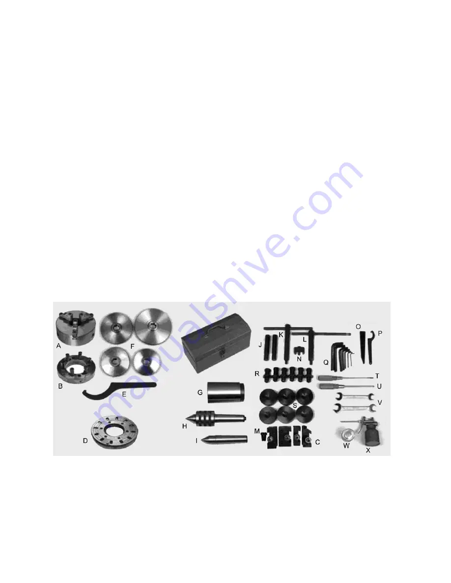
Contents of the Shipping Container
(Refer to Figure 3)
1 Lathe
2
Steady Rests (mounted on Lathe)
1
Follow Rest (mounted on Lathe)
1
Three Jaw Scroll Chuck, 12-25/32” (mounted
on Lathe)
– A
1
Drive Plate –
B
4 Tool Holder –
C
1
Face Plate, 24-25/32” (with 6 dogs) –
D
1
Round Nut Spanner, 170-210 mm –
E
4
Change Gears – 63T, 69T, 78T, 90T –
F
1
Tool Box, containing the following:
1
Morse Reduction Sleeve –
G
1
Live
Center,
MT-5
–
H
1
Dead Center, MT-5 –
I
2
Drive
Pins
–
J
1
Cam
Wrench
–
K
1
Chuck
Wrench
–
L
2 Hex Socket Head Cap Screw –
M
1
Gap Bridge Pin Driver –
N
1
Drift Key –
O
1
Round Nut Spanner (45-52 mm) –
P
1
Hex Key Set (2, 3, 4, 6,8,10,12 mm) –
Q
6
Leveling Bolts with Hex Nuts –
R
(qty. 8 for GH-26120ZH)
6
Leveling
Pads
–
S
(qty.
8
for
GH-26120ZH)
1
Flat Blade Screwdriver –
T
1
Cross Point Screwdriver –
U
2
Open End Wrenches (17/19,19/22) –
V
1
White Touch-up Paint Can –
W
1
Oil
Gun
–
X
1 Operating
Instructions
Manual
1
Parts List Manual
1
Warranty
Card
1 Test
Record
1
Packing
List
NOTE:
Optional accessories are available for JET Lathes, such as Taper Attachment, Collet Closer and
Digital Read Out. Contact your dealer or JET for more information.
Figure 3
ZH Series Lathes – Contents of Shipping Container
Summary of Contents for ZH Series
Page 34: ...34 18 0 Change Gear Diagram Figure 54...
Page 35: ...35 This page intentionally left blank...
Page 40: ...4 1 1 Bed Assembly I Exploded View...
Page 41: ...5 1 2 Bed Assembly I for 120 ZH only Exploded View...
Page 44: ...8 2 1 Bed Assembly II Exploded View...
Page 45: ...9 2 2 Bed Assembly II for 120 ZH only Exploded View...
Page 48: ...12 3 1 Headstock Assembly I Exploded View b b Z Z Z...
Page 51: ...15 4 1 Headstock Assembly II Exploded View...
Page 54: ...18 5 1 Headstock Assembly III Exploded View...
Page 56: ...20 6 1 Headstock Assembly IV Exploded View b...
Page 59: ...23 7 1 Headstock Assembly V Exploded View b...
Page 62: ...26 9 1 Gear Box Assembly I Exploded View...
Page 64: ...28 10 1 Gear Box Assembly II Exploded View...
Page 67: ...31 11 1 Gear Box Assembly III Exploded View...
Page 70: ...34 12 1 Brake Assembly Exploded View...
Page 72: ...36 13 1 Saddle and Cross Slide Assembly Exploded View...
Page 75: ...39 14 1 Tool Post and Compound Rest Assembly Exploded View...
Page 77: ...41 15 1 Apron Assembly I Exploded View...
Page 80: ...44 16 1 Apron Assembly II Exploded View...
Page 83: ...47 17 1 Apron Assembly III Exploded View...
Page 85: ...49 18 1 Apron Assembly IV Exploded View...
Page 87: ...51 19 1 Tailstock Assembly I Exploded View...
Page 89: ...53 20 1 Tailstock Assembly II Exploded View...
Page 91: ...55 21 1 Steady Rest Assembly Small and Large Exploded View...
Page 95: ...59 24 1 Travel Stop Assembly Exploded View...
Page 100: ...64 27 2 Electrical Diagram...


