27
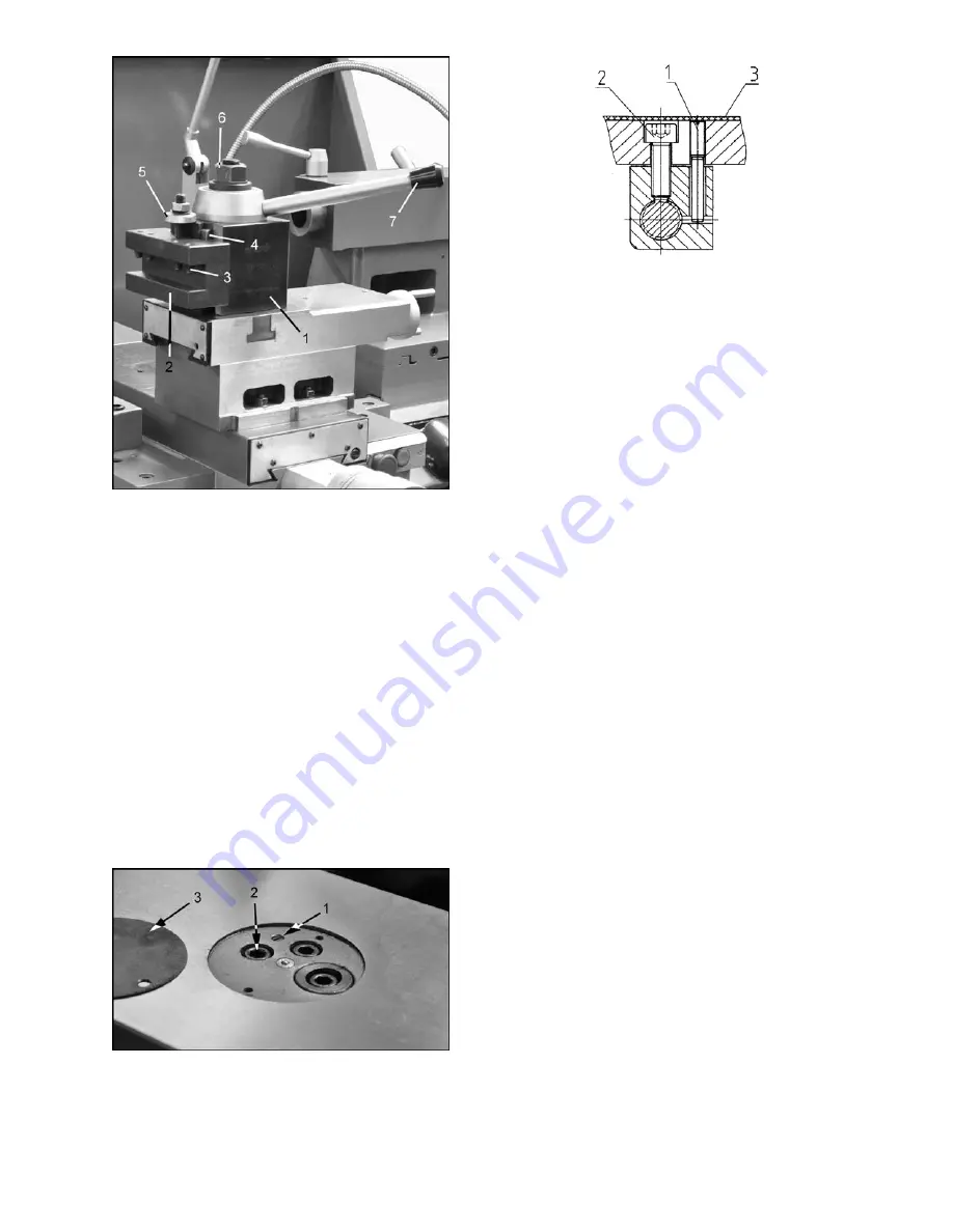
Figure 49 – Tool post adjustment
13.14
Cross Slide Nut Adjustment
The cross slide moves via a lead screw which
drives a nut. The nut is a half-split nut, allowing
slight adjustment if the cross slide becomes hard to
move or develops backlash. Backlash is identified
by turning the cross slide handwheel left and right
– if there is a delay before any cross slide
movement, the nut needs adjusting (Refer to
Figure 50).
1. Remove dust cover (3).
2. Loosen set screw (1).
3. Tightensocket head screw (2) until the play is
eliminated.
Do not overtighten, which may
cause excessive wear to components.
4. Retighten set screw (1).
5. Reinstall dust cover.
Figure 50 – Cross slide nut adjustment
13.15
Shear Pin Replacement
The lead screw and feed shaft are equipped with
shear pins, which are designed to break in order to
protect the drive system against overload. A
broken shear pin must be replaced.
Knock out the broken pin; line up the holes and
insert new pin.
13.16
Steady Rest Adjustment
Always grease the fingers before using the steady
rest. The point at which the fingers contact the
workpiece require continuous lubrication to prevent
premature wear.
To set the steady rest (see Figure 51):
1. Loosen the hex nut (A) at the base of the
steady rest, to slide the steady rest along the
ways.
2. Loosen the knurled handle (B) at the side until
it can be pivoted out of the slot.
3. Loosen the three lock knobs (C), and back off
the fingers (D) using the knurled handles.
4. Pivot the collar on its hinge and position the
steady rest around the workpiece.
5. Firmly tighten the hex nut at the base.
6. Set the fingers snugly to the work piece and
secure by tightening the locking knobs.
Fingers should be snug but not overly tight.
Summary of Contents for ZH Series
Page 34: ...34 18 0 Change Gear Diagram Figure 54...
Page 35: ...35 This page intentionally left blank...
Page 40: ...4 1 1 Bed Assembly I Exploded View...
Page 41: ...5 1 2 Bed Assembly I for 120 ZH only Exploded View...
Page 44: ...8 2 1 Bed Assembly II Exploded View...
Page 45: ...9 2 2 Bed Assembly II for 120 ZH only Exploded View...
Page 48: ...12 3 1 Headstock Assembly I Exploded View b b Z Z Z...
Page 51: ...15 4 1 Headstock Assembly II Exploded View...
Page 54: ...18 5 1 Headstock Assembly III Exploded View...
Page 56: ...20 6 1 Headstock Assembly IV Exploded View b...
Page 59: ...23 7 1 Headstock Assembly V Exploded View b...
Page 62: ...26 9 1 Gear Box Assembly I Exploded View...
Page 64: ...28 10 1 Gear Box Assembly II Exploded View...
Page 67: ...31 11 1 Gear Box Assembly III Exploded View...
Page 70: ...34 12 1 Brake Assembly Exploded View...
Page 72: ...36 13 1 Saddle and Cross Slide Assembly Exploded View...
Page 75: ...39 14 1 Tool Post and Compound Rest Assembly Exploded View...
Page 77: ...41 15 1 Apron Assembly I Exploded View...
Page 80: ...44 16 1 Apron Assembly II Exploded View...
Page 83: ...47 17 1 Apron Assembly III Exploded View...
Page 85: ...49 18 1 Apron Assembly IV Exploded View...
Page 87: ...51 19 1 Tailstock Assembly I Exploded View...
Page 89: ...53 20 1 Tailstock Assembly II Exploded View...
Page 91: ...55 21 1 Steady Rest Assembly Small and Large Exploded View...
Page 95: ...59 24 1 Travel Stop Assembly Exploded View...
Page 100: ...64 27 2 Electrical Diagram...


