9629 Microprocessor Controller
- 44 -
Section XII.
PCB Descriptions
Please refer to the illustration on the opposite page
for details of the parts and test points.
9600-10 Microcontroller Board
CONNECTORS
J1 - Power Supply Connector
The main 5VDC is supplied on this connector. If
there is no 5VDC, the unit will not operate.
J2 - Analog Input/Output Connector
This sends and receives the analog signals that are
on the 9600-11 board.
J3 - Keypad Connector
This allows the membrane style front panel to be
connected to the microcontroller.
J4 - Display Connector
This connects to the display which provides program-
ming and operational information.
J5 - Discrete Input/Output Connector
Connects to the 9600-11 board and transfers and
receives digital information.
J6 - Start/Stop Connector
Connects to the start and stop push-buttons to initiate
and end a weld sequence.
J7 - Serial Port Connector
This is unused in current 9629 models.
J8 - Encoder Connector
Connects to the encoder to receive pulses to incre-
ment and decrement the screen display.
J10 - Display Back Light Connector
Connects to the LCD display to permit the display
to be made more or less bright for better viewing in
various ambient lighting conditions.
COMPONENTS
U1 - Microcontroller
This is the main microcontroller of the 9629 control,
it sends and receives signals to and from all the vari-
ous devices on the board.
U3 - Digital to Analog Converter (DAC)
Receives digital information from the microcon-
troller and converts it to an analog value to control
the motor speed.
U6 - Non-Volatile Random Access Memory
(NVRAM)
All the calibration date, time delays and speed values
are held in this memory chip. To protect against
memory loss, this chip is battery-backed.
Note: If this chip is removed, all data will be lost.
U7 & U8 - Erasable Programmable Read Only
Memory (EPROM)
These two chips store the program which controls
the functions of the 9629 control.
U9 - Electronic Programmable Logic Device
(EPLD)
This unit decodes digital addresses so that the mi-
crocontroller can read and write to the other devices
on the board.
S1 - Reset Switch
This restarts the program sequence in the same way
as a power down at the main power switch.
JP1 - Jumper
The DAC can provide an output of 0 to 10V or +5V
to -5V. This jumper is factory set for your 9629
control and should not be changed without approval
from Jetline.
TEST POINTS
TP1 - Digital Ground
When measuring the digital level of signals of this
board, connect your isolated instrument ground lead
here.
TP2 - Analog Ground
When measuring the voltage of an analog channel,
connect the black lead of your meter here.
TP3 - Analog Channel 0
Connect the red lead of your meter here to measure
the analog signal from the tachometer. This value
has been scaled on the 9600-11 board.
TP4 - Analog Channel 1
This is unused and is reserved for future expan-
sion.
Summary of Contents for 9600 Series
Page 2: ...9629 Microprocessor Controller 2...
Page 6: ...9629 Microprocessor Controller 6...
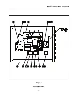
Page 41: ...9629 Microprocessor Controller 41 Figure 1 Enclosure SUB PANEL GROUND MAIN GROUND...
Page 43: ...9629 Microprocessor Controller 43 Figure 2 Enclosure Door...
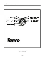
Page 49: ...9629 Microprocessor Controller 49 S1 CONNECTOR...
Page 50: ...9629 Microprocessor Controller 50 S2 CONNECTOR...
Page 51: ...9629 Microprocessor Controller 51 S3 CONNECTOR...
Page 52: ...9629 Microprocessor Controller 52...
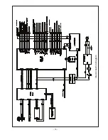
Page 53: ...9629 Microprocessor Controller 53 Interconnection Diagram...


