background image

Page 7

4. Clearance requirements -

Hebel installation up to 1050 sizes

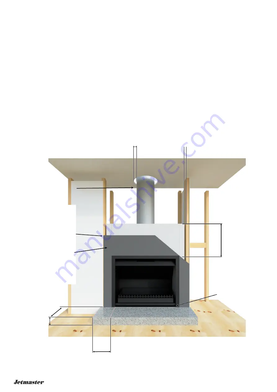
A hearth should be used under the appliance with a minimum depth of the ‘C’ measu 100mm to the rear and ‘A’ +
200mm in width and be centrally located. (refer section 2 components)

440 - 700 Must project forward of aperture by a minimum of 300mm.

* In the case of a hearth level (in-line) with a combustible floor material, projection to be extended by 100mm to a
minimum total of 400mm.

* 850 Must project forward by 400mm

* 1050 Must project forward by 500mm

Must project either side of aperture by a minimum of 200mm.

100mm minimum thickness

Includes finishing material if using 12mm sheet of fibre cement with a 50mm layer of Hebel Powerpanel 50.

The Thermal resistivity of the floor protector is 0.31m².K/W for 50mm thick Hebel Powerpanel.

Clay bricks (75mmx110mmx230mm) if used as a hearth must be laid on the 110mm edge combined with 12mm cement sheet.
(See joint AS/NZS 2918:2018 3.3.2). Bricks on the 75mm face is insufficient in terms of thermal resistivity to be compliant.

200mm

Brick/Hebel 600mm min.
above firebox.
Powerpanel 75 preferred
to reduce heat leakage
between joins.

50mm min. clearance to

outer flue to combustibles

Maintain 25mm air gap from
brick/hebel to any timber
framing.

Combustible cladding materials joining
to non-com should not be floating. Join
in the middle of studwork outside brick/
Hebel enclosure.

Non-combustible material up to outer
flange to 300mm above opening and
150mm to the sides.

If elevating unit above finished hearth
level, lower wall finishing must also be
non-combustible.

Ensure lower air intake is
not obstructed

*100mm

Fig 3.1

100mm 3 and 4 sided surrounds are available if greater coverage over cladding materials is required

440 - 700 = 300mm

850 = 400mm

1050 = 500mm

Summary of Contents for MARK 2 COAL 700SH LOW

Page 1: ... only Other fuels may over fire and generate poisonous gases i e carbon monoxide Do not store or use gasoline or other flammable vapors and liquids in the vicinity of this or any other appliance Do not over fire If appliance or chimney connector glows you are over firing Over firing will void your warranty Comply with all minimum clearances to combustibles as specified Failure to comply may cause ...

Page 2: ...uction and contents WARNING Page Section Information 2 3 1 Getting started 4 2 Components and specifications Unit and Gather 5 2 Components and specifications Surround Cowl Logpan and Screen 6 3 Timber framing specs All units 7 4 Clearance requirements Hearth 8 4 Clearance requirements Enclosure construction 9 5 Flue Chimney requirements General requirements 10 5 Flue Chimney requirements Installa...

Page 3: ... height of chimney between 14 16 feet 4 26 4 88m measured from the base of the appliance C Negative Pressure Negative pressure results from the imbalance of air available for the appliance to operate properly It can be strongest in lower levels of the house Causes include Exhaust fans kitchen bath etc Range hoods Combustion air requirements for furnaces water appliances and other combustion applia...

Page 4: ...uate outdoor air for all combustion appliances and exhaust equipment Ensure furnace and air conditioning return vents are not located in the immediate vicinity of the appliance Avoid installing the appliance near doors walkways or small isolated spaces Recessed lighting should be a sealed can design Attic hatches weather stripped or sealed Attic mounted duct work and air handler joints and seams t...

Page 5: ... 230 120 600 LOW 670 700 350 600 200 200 90 230 120 700S 770 800 350 650 200 200 90 230 120 700SH LOW 770 800 350 600 200 200 90 230 120 700 D 770 800 400 700 200 225 100 250 150 850 920 950 450 750 220 250 130 300 150 850 LOW 920 950 450 700 220 250 130 300 150 1050 1120 1150 500 800 240 300 150 320 180 1050 LOW 1120 1150 500 750 240 300 150 320 180 1050 LOW LOW 1120 1150 500 700 240 300 150 320 ...

Page 6: ...achieve a visual design and such cowls can be used but must not restrict airflow from the flue pipe casings For gas applications an AGA approved cowl must be used C D Measurements are in mm and provided as a reference only Due to the nature of thick welded steel it is normal and expected for some imperfections and slightly out of square components It is recommended to not begin construction of cav...

Page 7: ...50 1375 1170 575 850 LOW 1325 1170 575 1050 1425 1370 625 1050 LOW 1375 1370 625 1050 LOW LOW 1325 1370 625 Note Timber framing should be constructed using normal framing methods Image above is an example only Do not install finishing materials around the cavity until after the fireplace has been installed Frame height from top of the 100mm hebel hearth base Refer to the following page for hearth ...

Page 8: ...k Hebel Powerpanel Clay bricks 75mmx110mmx230mm if used as a hearth must be laid on the 110mm edge combined with 12mm cement sheet See joint AS NZS 2918 2018 3 3 2 Bricks on the 75mm face is insufficient in terms of thermal resistivity to be compliant 200mm Brick Hebel 600mm min above firebox Powerpanel 75 preferred to reduce heat leakage between joins 50mm min clearance to outer flue to combustib...

Page 9: ... to outer flange to 300mm above opening and 150mm to the sides Optional 3 or 4 sided 100mm surrounds are available If elevating unit above finished hearth level lower wall finishing must also be non combustible Clearance to an adjacent wall for units 440 1050 and should be installed to 1200mm as per clause 3 2 2 b 2918 2018 Wrap entire firebox and gather in 25mm fibreglass insulation to 200mm abov...

Page 10: ...ation cap away from trees adjacent structures uneven roof lines and other obstructions Your local dealer is the expert in your geographic area and can usually make suggestions or discover solutions that will easily correct your flue problem Minimum height of flue system exit Solid fuel AS NZS 2918 2018 NOTICE Chimney performance may vary Trees buildings roof lines and wind conditions affect perfor...

Page 11: ...er at crimped joins Fix outer non active flues to active inner flues use 3 x 25mm self tapping screws through outer flue at bottom at each join and on top at each join As an alternative rivet 4 x 25mm conduit saddles at each join top and bottom Ventilate the flues cut 4 x 25mm notches at bottom of first length of outer flue and top of outer flue in either the ceiling cavity or just below the ceili...

Page 12: ...it is suggested an experienced builder to do the work as the sides support inner flues of the chimney NOTE Allow 1 5mm expansion gap for all materials 3 Repair any cracks or cavities in the recess especially if it has been chopped out to accommodate a specified unit size and the cavity between a double brick wall has been exposed Note No metal gather or flue is required if the chimney passes a smo...

Page 13: ... masonry overhangs the smokeholes ensure at least 200mm clearance above the unit Ensure seal between brick edge and firebox front optional surround likely required to assist forming this seal as per below Fibreglass insulation to be packed all around firebox Do not cover smoke outlets Optional surrounds available to cover this gap No surround With optional surround to cover opening ...

Page 14: ...t side towards you with the steel handle provided 2 In firebox lay your fire lighters 10 to 15 centimetres apart depending on the size of your firebox Do not use newspaper as a fire lighter On units that are installed with a dual spigot gather it is recommended to light 2 fires directly underneath the two separate flues 3 Add soft wood kindling in a criss cross pattern above the firelighters Softw...

Page 15: ...AS NZS 2918 General notes Fuels The quality of firewood is extremely important How long a tree has been felled or dead for does not indicate how dry the wood is The best way to dry wood is to split it and expose the inner core allowing the sun to dry the wood naturally Good wood merchants will split the wood for you but may not season it for you The amount of you pay for your wood does not justify...

Reviews: