Page 9
Bullfrog Spas Owner’s Manual
ELECTRICIAN'S INSTRUCTIONS:
NOTICE:
As of January 1, 1994, the National Electric Code (Article 680-42) requires that all spas, hot tubs, and
associated electrical components shall be protected by Ground Fault Circuit Interrupters.
Providing 120 Volt Service to the Bullfrog Portable Spa:
As per code, supply a GFCI protected, 3-wire (Line 1,
Neutral & Ground), 20-AMP, 60HZ, Single-Phase service to the front, left corner (when you are facing the control
pad) of the Bullfrog Portable Spa. This service must include a disconnect that is visible from the spa and located
not less than five feet from the spa and not more than 50 feet from the spa (a GFCI Sub-Panel may be used to
substitute the disconnect if located within the same parameters).
Providing 240 Volt Service to the Bullfrog Portable Spa:
As per code, supply a GFCI protected, 4-wire (Line 1,
Line 2, Neutral & Ground), 50-AMP, 60HZ, Single-Phase service to the front, left corner (when you are facing the
control pad) of the Bullfrog Portable Spa. This service must include a disconnect that is visible from the spa and
located not less than five feet from the spa and not more than 50 feet from the spa (a GFCI Sub-Panel may be used
to substitute the disconnect if located within the same parameters).
Installation of the GFCI:
All conductors except the green ground must be routed through the GFCI, including the
neutral. Never bypass the neutral line. If the neutral line is bypassed, then the current will be imbalanced and
cause the GFCI to trip.
Note:
For a GFCI wiring diagram, please contact Bullfrog International, L.C. or an authorized Bullfrog Portable Spa
Dealer.
Connecting the Spa:
1. Remove the equipment compartment door.
2. Remove the face-plate to the Control Center by removing the four screws located in the front.
3. Connect a 1" non-metallic coupling and conduit to the 1" male CPVC pipe found at the base of the spa cabinet
(see “Parts Identification Diagram” in this manual).
4. Run the required wires through the conduit and to the Control Center.
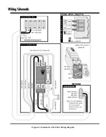
5. Connect the 3 wires (120V systems)/4 wires (240V systems) to the terminal block located in the Control Center
(see appropriate “Wiring Diagram”).
6. Replace the Control Center face-plate and the equipment compartment door.
7. The electrical hook-up is complete.
Important:
Do not fill or start-up the spa until you have completed the following section.


