Diagnos e s
During engine operation the Ecu measures and stores all the engine operating parameters recorded during the
last the 51 minutes of operation. These measures can be downloaded later to a PC to study the behaviour of the
engine in flight and to diagnose any possible problems.
Also, after each cycle of operation, the Ecu stores the last cause of shut down and the values of RPM, temperature
and pump power. In order to access these measures, it is necessary to shut down and power-up the Ecu. Set the
trim down (trim Low) and push the left button on the display. The Ecu will show the cause of shutdown and the
parameter values at the moment of shut down. These are as follows:
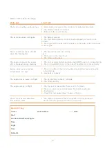
Diagnosi s mess a g e s
UserOff:
FailSafe:
The engine has been shut down because it has received the shut down command from the
transmitter.
The engine has been shut down because of loss of the control signal from the transmitter. After
0,5sof detecting a loss or invalid RC signal, the ecu sets engine power to idle, and if after another
1,5 seconds a valid signal is still not received the engine is shut down.
The engine has been shut down because the RPM has dropped below a minimum. Cause could
be lack of fuel, air bubbles, problem with the batteries, or defective RPM sensor.
The engine has been shutdown because the temperature has dropped below the minimum of
(100ºC).(Usually a thermocouple failure).
Lack of power from the radio receiver.
LowRP M:
FlameOut:
RCPwF ail:
Other useful information and installation tips
Fuel System
Always use appropriate containers to store fuel.
It is advisable to install an antibubble system to the fuel supply
circuit.
The simplest one is a felt filter clunk installed into the fuel tank.
This helps maintain consistent fuel flow and greatly reduces the
possibility of air getting into the suction side of the pump circuit,
which could cause stoppages.
To prevent the felt element sliding out of position a washer is fitted
between it and the feed tube – as seen.
A BVM UAT is another contemporary method
of reducing the possibility of air bubbles in the
engine fuel line. This is a very important as-
pect of the operation of any turbine engine.
Use a appropriate adapter for the 6 mm tube
output of the UAT to the 4 mm in the inlet
side of the fuel pump, direction of fuel flow
is clearly shown at the top of the pump. The
clear 4 mm tubing is used on the pressure
side of the pump. Clear tubing helps identify
and locate any potential future problems with
air leaks.
15


