


5
Schalbrett /
/
shutterung planche de coffrage
Beton /
/ béton
concret
Wasserspiegel /
water level /
niveau de l'eau
Schild “oben" /
étiquette “haut”
label “top”
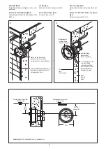
24
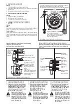
Kabelschutzschlauch für Beleuchtungskabel
du câble pour d’illumination
Protective sleeve forillumination
(optimal 28,7)
23,7 - 38,7
25,6
Ø 31
Ø
28,9
Kabelschutzschlauch /
Gaine de protection du câble
Protective sleeve
Spezialnippel nicht ausschrauben
Raccord spécial ne pas remplacer
Special nipple do not remove
Saugstutzen /
Manchon d'aspiration
Suction duct
Druckstutzen /
Manchon de raccordement pression
Presure duct
Luftansaugschlauch 4 m lang
Tuyau d'aspiration de air 4 m
Air inlet tube 4 m long
Mittelachse der Düse /
niveau de la buse
nozzle center line
Sechskant-Schraube M 8 x 50
hexogonal M 8 x 50
shuttering screw M8 x 50
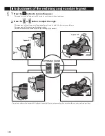
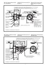
vor dem Fliesen Schutzkappen abziehen
avant la carrelage retier le couvercle
de protection
remove protective cover before rendering
Düsenmantelgehäuse /
pièce à sceller
wall niche
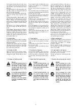
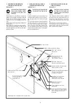
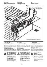
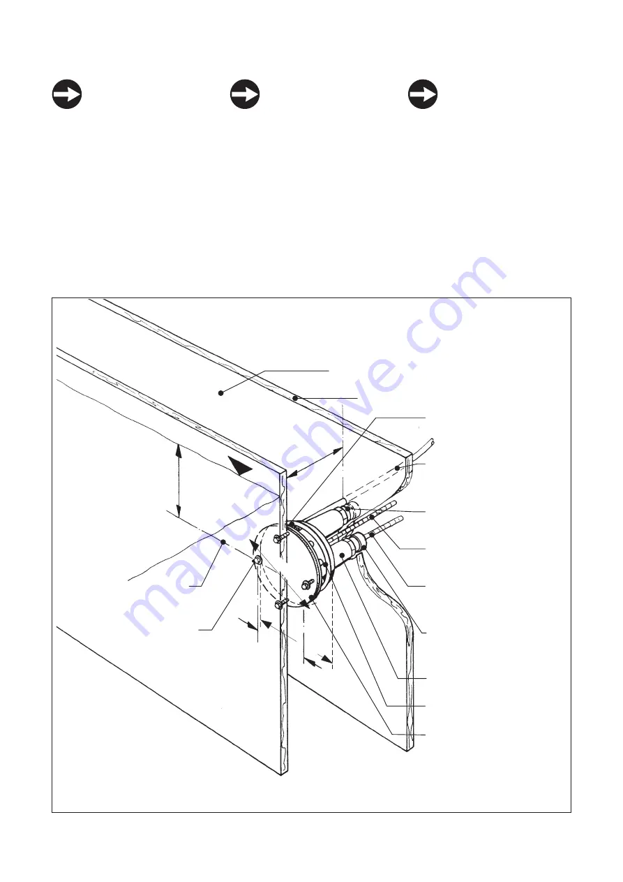
2 EINSETZEN DES DÜSENMANTEL
GEHÄUSES IN DIE SCHALUNG
Montage (Bild 1)
Schrauben Sie das Düsenmantelge-
häuse so in die Schalung, daß das
rote Schild mit Text „oben“ nach
oben zeigt.
Dann befindet sich, von der Beckeninnenseite her
gesehen, der Druckstutzen auf der senkrechten Mit-
telachse über dem Gehäusemittelpunkt, der Saug-
stutzen rechts unten, der Luftansaugschlauch links
oben.
Setzen Sie das Düsenmantelgehäuse bündig mit der
Beckenwand ein.
Erhält das Becken für eine Folienauskleidung einen
Putz- oder Dämmplattenauftrag, so müssen Sie das
Düsenmantelgehäuse um die Putz- bzw. Dämmplat-
tenstärke vorziehen.
1
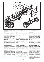
Funktion
2 INSTALLING THE WALL NICHE IN
CONCRETE SHUTTERED POOLS
Installation (fig. 1)
Position the wall niche ensuring that
the read label “Oben” (top) is on top.
Viewed from inside the pool, the suction duct is on
the vertical middle axis above the center of the hou-
sing, the pressure duct at the bottom on the right
side.
The front of the wall niche must be set flush with the
face of the wall concrete. In case of a liner/concrete
pool, the wall niche may project in order to compen-
sate for the cement render of liner insulation thick-
ness. It is advisable to make provision for protecting
tube by placing in protective conduit or through ad-
jacent cable/ventilation ducts.
2 MONTAGE DE LA PIÈCE À SCELLER
DANS LE COFFRAGE
Montage (fig. 1)
Positionner la pièce à sceller dans
le coffrage de telle manière que
l’étiquette rouge „haut“ (Oben) se
trouve en haut.
Vu de l’intérieur du bassin,le tuyau de refoulement
se trouve alors sur l’axe vertical au-dessus du cen-
tre du boîtier, le tuyau d’aspiration se trouve en bas
à droite, le tuyau d’aspiration d’air en haut à gau-
che.
Monter le boîtier à ras avec la paroi de béton.
Si le bassin reçoit pour son revêtement liner des
plaques d’enduit et d’isolation, il faut avancer le boî-
tier de l’épaisseur de ces plaques.
Function
Fonction
Abmessungen in cm /
dimensions in cm
/ mesures en cm