30
Operation Manual
5. Once properly adjusted, system pressure
can be raised for waterblasting.
6. 5200 pump differences: The plumbing
arrangement is slightly different on the
5200 power end. It is located in the rod
box and the adjustable flow controls are
integrated into the elbow fittings (Figure
32).
Raising System Pressure
1. With both engines running and transmis-
sions in gear, raise the engine speed of
either enginer to 1400 rpm, followed the
second engine, by pressing the throttle up
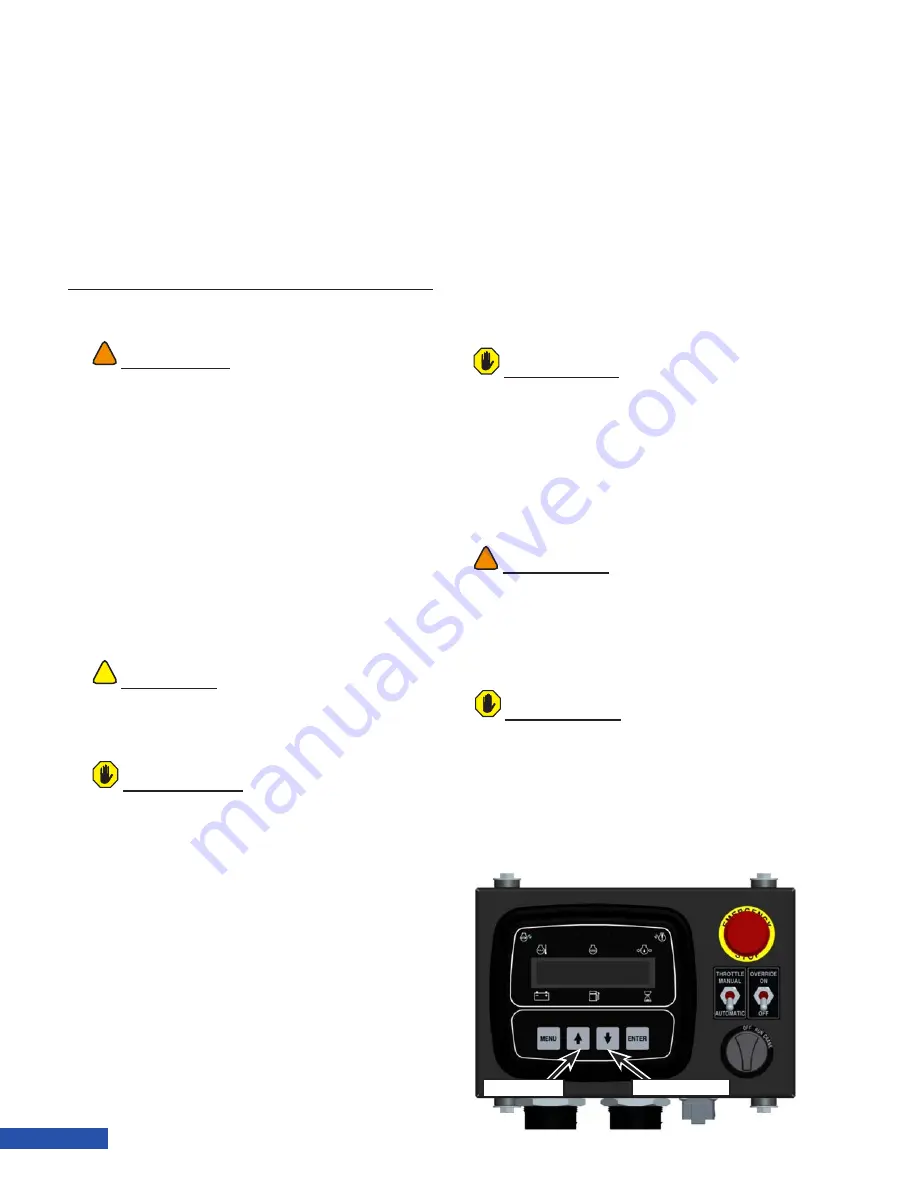
button (Figure 39) on the control panel(s).
2.
Both bypass valves on each fluid end (If
equipped) should be completely closed.
Pressure control will be made at the rear
of the trailer from the single bypass de-
vice in which both output hoses from the
WARNING
!
!
Before building pressure, contain the high pressure
discharge hose. Failure to contain and control the
high pressure water can result in death or serious
injury. The water is considered “contained” if it
is allowed to discharge from the system through
a “manned” control gun or a “manned” lance
inserted in a tube. Control guns can produce a
tremendous amount of reverse thrust based on
flow and pressure.
Discharge must be in an enclosed space where
no one can get injected and the end of the hose is
restrained from moving.
Never use open lengths of high pressure hose for
anything but purging at low pump speed.
Install whip checks at all hose connections.
!
!
CAUTION
When operating in cold temperatures, allow
ample time for the pump oil to warm before
raising system pressure.
ATTENTION
If new packing was installed or if operating the
pump for the first time, the pump packing must
be broken in properly. Refer to “Breaking In New
Packing” for instructions.
pump fluid ends are entering. Slowly turn
the bypass valve clockwise to start clos-
ing the bypass and build pressure.
3. Slowly increase pressure by increasing
engine rpm by 300 rpm on each engine at
a time until the intended operating pres-
sure and flow is obtained. Optimal engine
speed for operation is between 1400-2100
rpm. The control panel prevents the unit
from exceeding the maximum rpm al-
lowed by the pump. Both engines should
run at the same speed.
ATTENTION
Always blast with the bypass valve fully closed.
This will ensure the most efficient operation with
all water being utilized. If less water volume is
required, reduce the engine rpm to control the
flow amount. If bypassing flow is necessary, the
bypass valve cartridge and the bypass valve
diffuser will wear and these parts may need
replacing regularly. Bypassing water also wastes
water and wastes fuel as this is lost horsepower.
WARNING
!
!
Do not operate the pump under a load at engine
speeds below 1400 rpm. This will lug the engine
and cause excessive vibration leading to engine
damage and cracked brackets, guards and
fittings.
Throttle Down
Throttle Up
Figure 39: Throttle Controls.
ATTENTION
Slight variation in the consistency of pressure
fluctuations may be noticed at the outlet pressure
gauge as the pump synchronization moves in
and out of phase. This should not be confused
with large intermittent drops and recovery of the
pressure at the gauge, which could be a sign of
blown packing and/or other operational issues
with the equipment.
Summary of Contents for TwinForce Series
Page 1: ...OPERATION MANUAL TwinForce Series Waterblast Unit...
Page 2: ...Visual Safety System...
Page 11: ...3 TwinForce Series Waterblast Unit...
Page 22: ...14 Operation Manual...
Page 42: ...34 Operation Manual...
Page 48: ...40 Operation Manual...
Page 52: ...44 Operation Manual...
Page 100: ...92 Operation Manual...
Page 104: ...96 Operation Manual...
Page 106: ...A 2 Appendix A Technical Specifications...
Page 107: ...B 1 TwinForce Series Waterblast Unit APPENDIX B LONG TERM STORAGE PROCEDURE...


