© 2018 Jetta Corporation. All rights reserved. REV 03/2018
1(800) 288-7771
INSTALLATION INSTRUCTIONS | JETTA CORPORATION
PAGE | 3
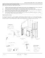
GENERAL INSTALLATION INSTRUCTIONS
ELECTRICAL
WARNING
– WHEN USING ELECTRICAL PRODUCTS, BASIC PRECAUTIONS SHOULD ALWAYS BE FOLLOWED, INCLUDING THE
FOLLOWING:
DANGER: RISK OF ELECTRIC SHOCK.
CONNECT ONLY TO A CIRCUIT PROTECTED BY A GROUND-FAULT CIRCUIT-
INTERRUPTER. GROUNDING IS REQUIRED. THE UNIT SHOULD BE INSTALLED BY A QUALIFIED SERVICE REPRESENTATIVE AND
GROUNDED. (FOR BUILT-IN AND CUSTOM UNITS) INSTALL TO PERMIT ACCESS FOR SERVICING.
1. This unit must be connected to a supply circuit that is protected by a ground-fault-circuit-interrupter (GFCI). Such a GFCI should be
provided by the installer and should be tested on a routine basis. To test the GFCI, push the test button. The GFCI should interrupt
power. Push the reset button. Power should be restored. If the GFCI fails to operate in this manner, there is a ground current
flowing indicating the possibility of an electric shock. Do not use this unit. Disconnect the unit and have the electrical problem
corrected by a qualified service representative before using.
2. Disconnect power before servicing.
3. The motor is supplied with a 30”, 14-gauge U.L. approved pigtail. This pigtail is installed at the manufacturers facility and is factory
tested and should not be removed or altered under any circumstances. Removal or alteration of this pigtail will void the warranty. The
green lead of the pigtail is connected to the ground terminal inside the terminal compartment. To reduce the risk of electric shock, you
must ensure that your electric service or supply panel is properly grounded with a continuous green insulated copper wire equivalent in
size to the circuit conductors supplying this equipment, but no smaller than No. 12 AWG.
4. A pressure ground connector is provided on the exterior of the terminal box within this unit to permit connection of a No. 8 AWG solid
copper bonding conductor between this unit and all other electrical equipment and exposed metal in the vicinity as needed to comply
with local requirements.
5. Install to permit access for servicing (for built-in and custom units).
6. Installer / Owner bears all responsibility to comply with all state and local codes when installing this product.
TESTING:
Water test your unit prior to installation. Set the tub on a level surface where it can be drained after testing. Insert drain fitting and fill
to the overflow. Make sure all fittings, through walls and piping are water tight. While each unit is leak tested at the factory, the process
of shipping and handling may loosen joints. If there are leaks, mark the spot(s), drain and repair with GE Silicone Sealer (fiber glass to
PVC) or PVC cement (PVC to PVC). Repeat test when dry.
Summary of Contents for RAIN SHOWER BASES
Page 2: ......


