2.5
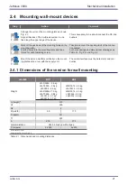
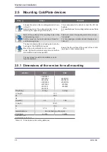
Mounting ColdPlate devices
Step
Action
Comment
1
1
.
.
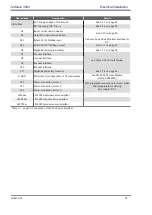
Arrange the units on the mounting plate as shown
Align all devices of the multi-axis system in one
line along the upper edge of the device.
This is necessary to be able to connect the DC link
busbars.
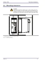
For specifications for mounting
distances see Table
2
2.
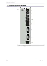
Mark off the positions of the mounting holes on the
corresponding cooler.
Drill the holes into the cooler and tap a thread for
each fastening screw.
Take into account the bending radii of the connec-
tion cables!
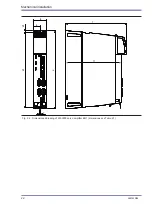
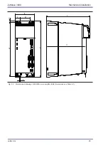
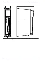
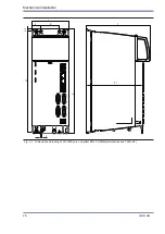
For hole spacings and dimensional drawings see
3
3.
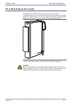
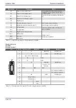
The heat conducting film is already glued onto the
back wall of the ColdPlate devices.
Mount the units vertically and in a row on the
cooler. Tighten the screws evenly to keep the ther-
mal resistance as low as possible.
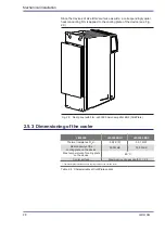
Ensure that the surface of the cooler is free of drill-
ing chips or other contaminants.
The next steps for electrical installation can be
2.5.1
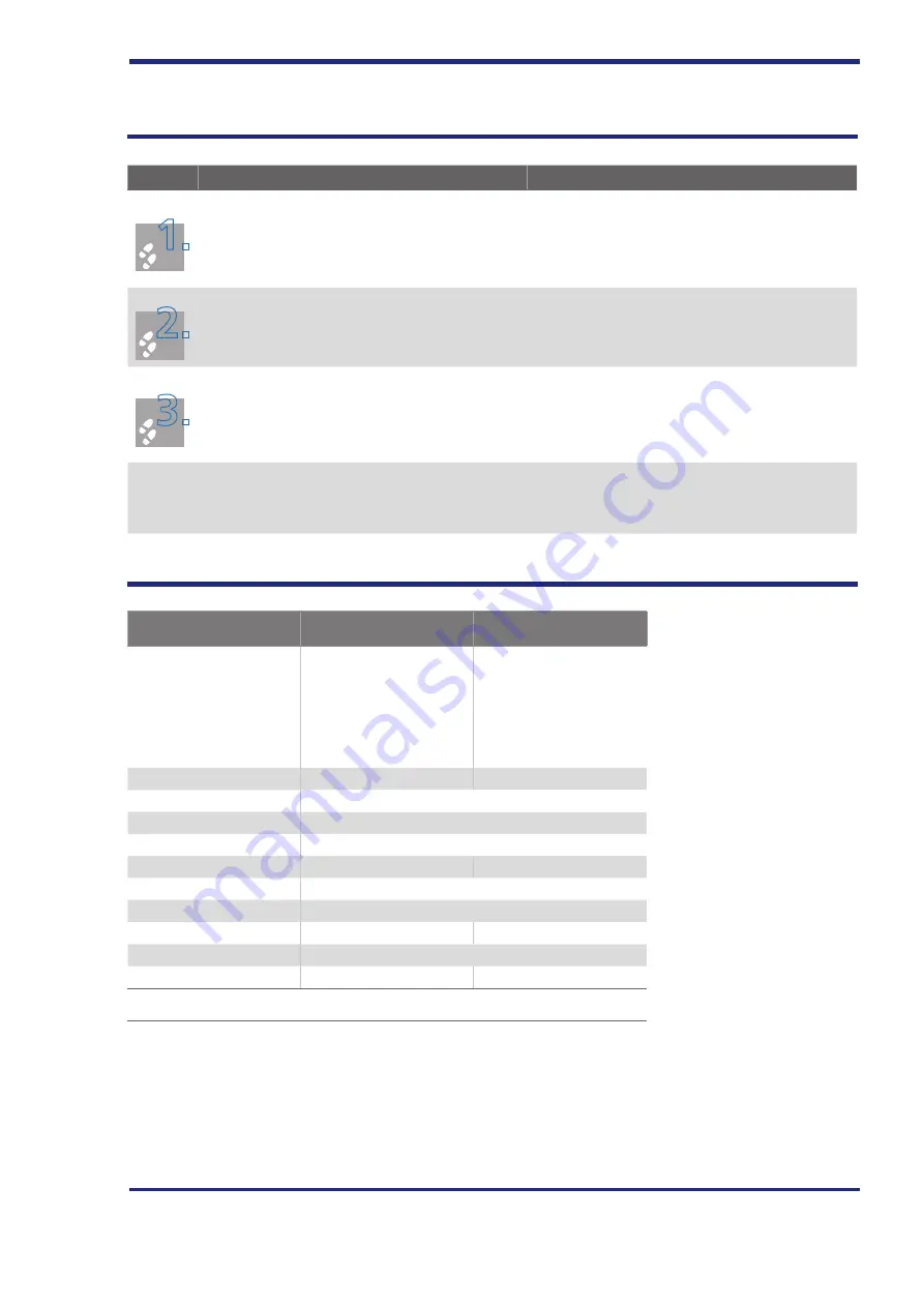
Dimensions of the version for wall mounting
JM-3000
BG1
BG2
JM-D3503
JM-T3503
JM-3506
JM-D3506
JM-T3506
JM-3512
JM-3518
JM-D3512
JM-T3512
JM-D3516
JM-3524
JM-3532
Weight [kg]
2.2 kg|
4.2 kg|
H (height)
310
H1
299
H2
6
W (width)
55
109
D (depth)
188.5
T1
170
A
27.5
27.5
Lateral distance
Can be lined up without gap
C (screws)
2 x M4
4 x M4
All dimensions in mm
Drawing see Fig. 2.3 and Fig. 2.5
Table 2.2 Dimensions and mounting distances
Mechanical installation
24
Jetter AG


