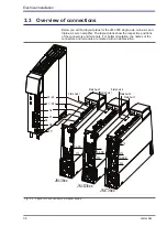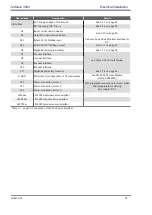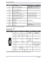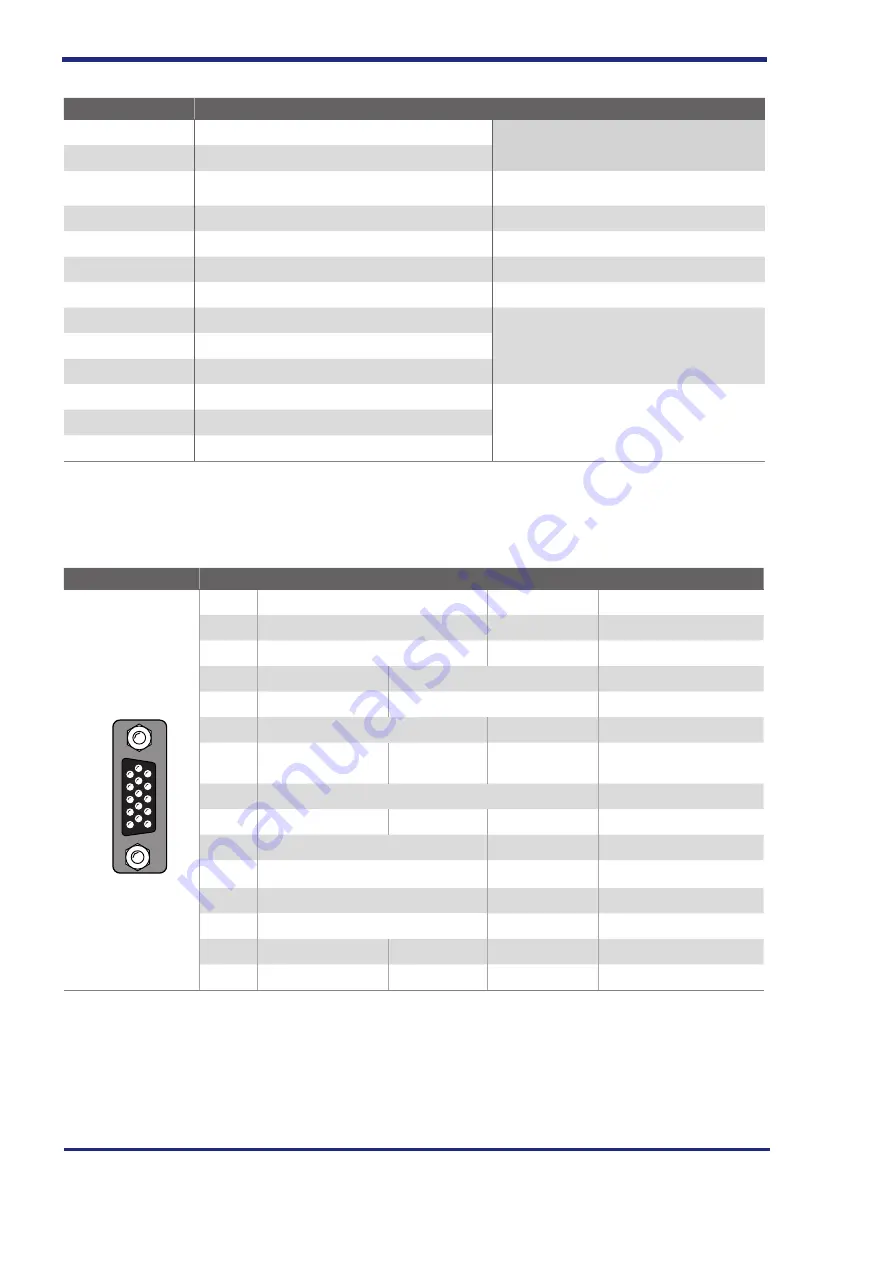
Abbreviation
Designation
Details
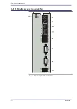
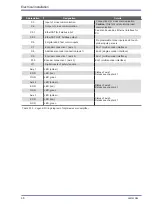
X3
Cross communication input
Connections for cross communication.
Caution
: Only for system-internal use/
communication
X4
Cross communication output
X5.1
EtherCAT IN, fieldbus input
Can also be used as Ethernet interface for
PC.
X5.2
EtherCAT OUT, fieldbus output
X6
Digital inputs
X7
Encoder connection 1 (axis 1)
Enc1 (multi encoder interface)
X8
Additional encoder connection (axis 1)
Enc2 (single encoder interface)
X9
Not applicable
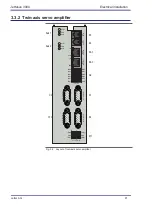
Used only with twin-axis and triple-axis
servo amplifiers.
X10
Not applicable
X11
Digital inputs of safety function
Axis 1
LED (amber)
Status of axis 1
ERR
LED (red)
RUN
LED, green
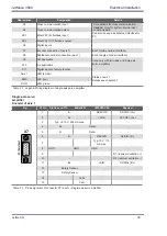
Table 3.2
Legend: Wiring diagram of single-axis servo amplifier
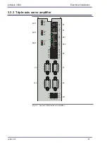
Single-axis servo
amplifier
encoder of axis 1
Fig.
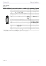
X7 Pin SinCos and ttl
enDat/SSI
HIPeRFACe®
Resolver
54321
10
9876
15
14
13
12
11
X7
X7 / Axis1Enc
1
1
A-
REFCOS
S3/COS- (A-)
2
A+
+COS
S1/COS+ (A+)
3
Typ. +5.15 V, 250 mA max.
-
-
4
R+
Data+
-
5
R-
Data-
-
6
B-
REFSIN
S4/SIN- (B-)
7
-
-
Typ. 10 V, 110
mA max.
-
8
GND
GND
GND
-
9
-
-
-
R1 (resolver exci)
10
-
-
R2 (resolver excitation -)
11
B+
+SIN
S2/SIN+ (B+)
12
Safety Sense+
-
-
13
Safety Sense-
-
-
14
-
CLK+
-
-
15
-
CLK-
-
-
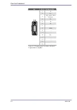
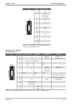
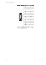
Table 3.3
Pin assignment of connector X7 (Enc1) - Single-axis servo amplifier
Jetter AG
39
JetMove 3000
Electrical installation

