3.5
electrical isolation concept
All control connections are designed as a safety extra-low voltage circuits
(PELV) and must only be operated with such PELV voltages according to
the respective specification. This means a secure protection from electric
shock on the control side.
The connections DC Link +/-, X12 - U/V/W, X13 - U/V/W and X14 - U/V/W
are at mains potential (low voltage).
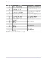
The following overview details the potential references of the individual
connections.
This concept also achieves a higher operational reliability of the servo
amplifier.
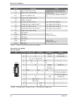
Servo amplifier connections (12)
Description
Potential
Abbrevia-
tion
Busbar 24 V DC
Supply voltage of control
section
Protective extra-low voltage
circuit
3)
PELV
Busbar DC link
Supply voltage
DC link
Low voltage
1)
ZK
X3/X4:
Cross communication
Protective extra-low voltage
circuit
3)
PELV
X5.1/X5.2:
EtherCAT IN/OUT fieldbus
connection
Protective extra-low voltage
circuit
3)
PELV
X6/DI
Digital control inputs
Protective extra-low voltage
circuit
3)
PELV
X11/Safe - DI
Safe digital inputs
Protective extra-low voltage
circuit
3)
PELV
X7/X8/X9/X10
Encoder connections
Protective extra-low voltage
circuit
3)
PELV
BRK - X12/X13/X14
Motor holding brake con-
nection
Protective extra-low voltage
circuit
3)
PELV
ϑ motor - X12/X13/X14
Motor temperature sensor
connection
Basic insulation
2)
BI
U/V/W - X12/X13/X14
Motor phase connections
Low voltage
1)
ZK
1) Low voltage = AC: U ≤ 1000 V
2) Simple isolation from low-voltage and PELV network
3) PELV (Protective Extra Low Voltage) = protective low voltage AC: U ≤ 50 V
One connection of the extra low voltage is grounded.
4) Secure isolation from low-voltage and PELV network
Table 3.15 Key to "Electrical isolation concept" overview
Electrical installation
52
Jetter AG

