3.10 Specification of cross communication
Desig.
term.
Specification
Fig.
XC IN
Cross communi-
cation input
X3
•
Connection via RJ10 connec-
tor
•
Internal RS-485 network
1
15
1
15
1
15
1
15
L/A
RUN
L/A
ERR
Axis 1
ERR
RUN
Axis 2
ERR
RUN
Axis 3
ERR
RUN
DI00
DI01
DI02
DI03
DI04
DI05
DI06
DI07
DI08
DI09
DI10
GND
X6 / DI
X3 XC IN
X4
XC OU
T
X5.1
ECA
T iN
X5.2
ECA
T OU
T
X7 /
Axis1Enc
1
X9 /
Axis2Enc
1
X8 /
Axis1Enc
2
X10 /
Axis3Enc
1
SDI00
SDI02
GND
GND
SDI01
SDI03
X11 / Safe - DI
X6
X7
X8
X11
X3
X4
X5.1
X5.2
Achse 1
Achse 2
X9
X10
Achse 3
Statusanzeige:
1)
1)
Siehe Kapitel
5 Diagnose
111
1555
111
1555
L/
RUN
L/A
ERR
Axis 1
ERR
RUN
Axis 2
ERR
RUN
Axis 3
ERR
RUN
DI00
DI01
DI02
DI03
DI04
DI05
DI06
DI07
DI08
DI09
DI10
GND
X6 / DI
EC
X5.
2
ECA
T OU
T
X7
/ Axi
s1En
c1
X9 /
Axis2Enc
1
X6
X7
X5.1
X5.2
Achse 1
Achse 2
X9
Achse 3
Statusanzeige:
1)
XC OUT
Cross communi-
cation output
X4
Table 3.22 Cross communication
NotICe
These connections are used exclusively for internal communication be-
tween the supply unit and the servo amplifiers. Connections must be made
before commissioning, otherwise error messages will occur.
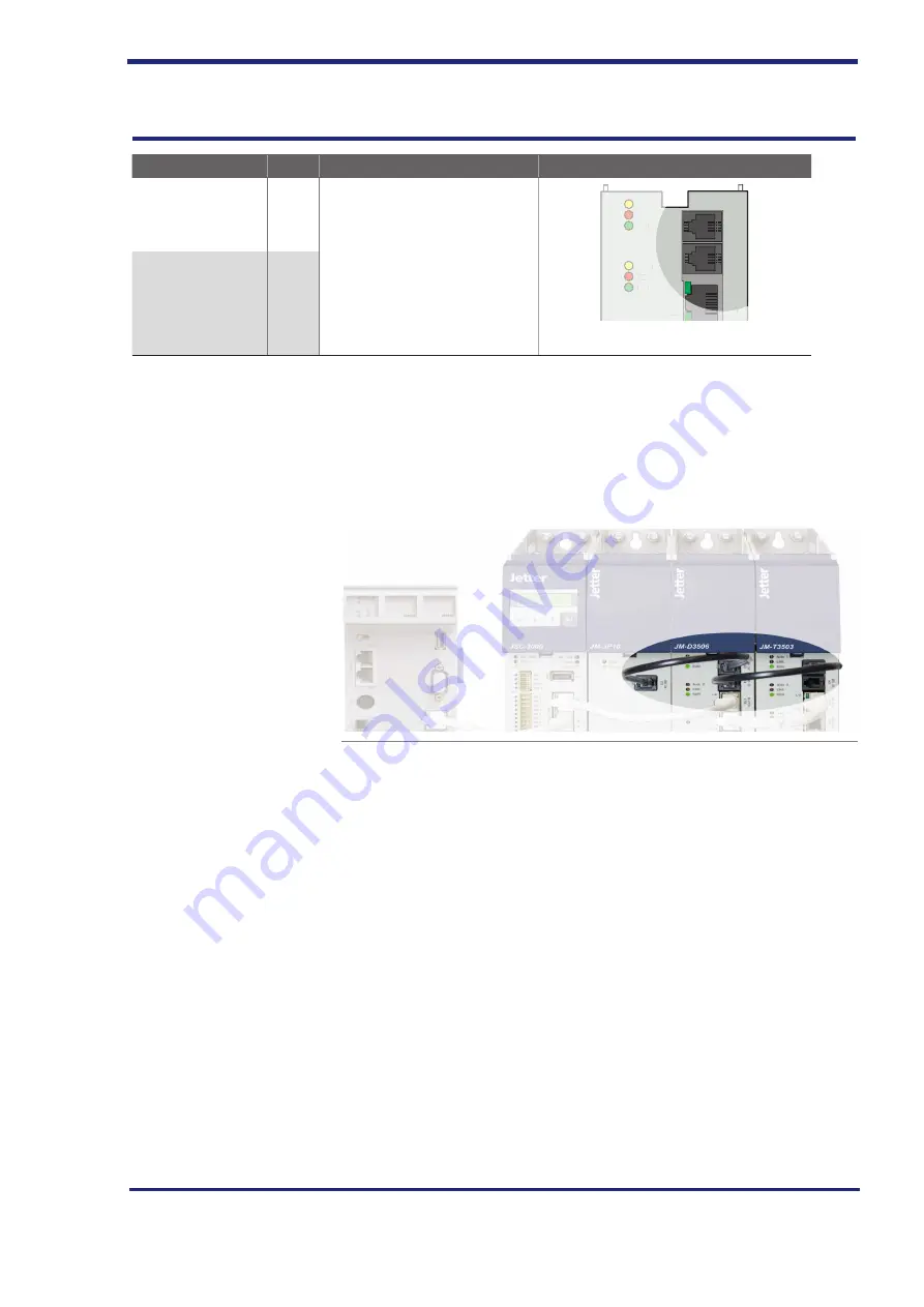
Connection example:
Fig. 3.15 Connection example of cross communication
Electrical installation
66
Jetter AG


