3.8
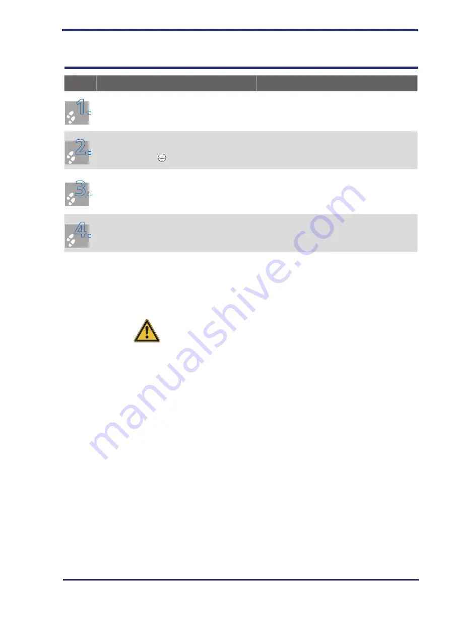
Connecting the motor
Step
Action
Comment
1
1
.
.
Define the cable
cross-section depending on the
maximum current and ambient temperature.
Select the cable cross-section in accordance with
local and country-specific regulations and condi
-
tions.
2
2.
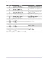
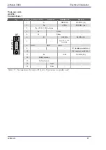
Connect the shielded motor cable to terminals
X12/X13/X14 - U, V and W. Ground the motor at
the ground terminal .
Shielding to reduce interference signals; connect
shield at both ends. Fasten the shield clamp of
the motor terminal X12/13/14 with
both
screws.
3
3.
Connect the temperature sensor (if present) to
X12/13/14 with separately shielded cables and
activate the temperature monitoring using Drive-
Manager 5.
Shielding to reduce interference signals; connect
shield at both ends.
4
4
.
.
Connect the motor holding brake, if any, to X12/
X13/X14 - 1 and 2.
Note:
Only use motors that allow a connection of the motor temperature sensor
exclusively to the motor terminals X12/13/14 of the servo amplifier. This
must be expressly stated when ordering a motor.
CAUtIoN
If a ground fault or short circuit occurs in the motor cable during opera-
tion, the output stage is disabled and an error message is sent. The motor
coasts to a stop.
Electrical installation
60
Jetter AG


