Jetter AG
Electrical connection | 6
User Manual – JetViewMobile 205
19
6 Electrical connection
WARNING
Signal disruption due to incorrect CAN wiring
Unshielded or incorrectly twisted CAN lines may cause com-
munication faults. In the worst case, a malfunction of the de-
vice can lead to subsequent physical injury.
►
Connect 120 Ω termination resistors to both ends of the
CAN bus.
NOTICE
Damages to material or functional impairment
Improper implementation of the wiring harness may cause
mechanical stress.
►
Protect the cables from bending, twisting or chafing.
►
Install strain reliefs for the connecting cables.
NOTICE
Surges resulting from missing protection or fusing
Surges may cause malfunctions or damage to the product.
►
Protect the voltage inputs from surges according to the
requirements.
►
Ensure that the device is handled in accordance with
ESD regulations.
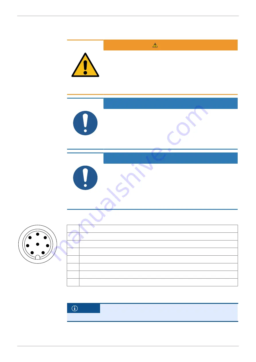
6.1 8-pin M12 connector (male)
2
1
7
5
6
4
3
8
Fig. 6: 8-pin M12 plug
1
Power supply term.30 (+12 V)
2
USB data tr
3
Ignition input/output (max. 0.5 A)
4
USB data transfer -
5
CAN-L
6
Power supply term. 31 (GND)
7
CAN-H
8
USB +5 V (USB_VBUS)
Tab. 18: Pin assignment of the M12 plug
INFO
To use the USB signal, the use of a cable T-piece is recom-
mended.


