background image


Jetter AG 

93 


JVM-507B 

Programming 

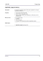
Application program memory 

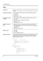
By default, the application program (STX script) is uploaded from JetSym to 

the HMI and is stored to it. 


Stored as file within the file system 


Default directory 

\app\program name


Files may also be stored to other directories (or on SD memory card or 

USB flash drive) 


By operating system 


By JetSym 


Via FTP connection 


By means of file commands from within the application program 


Application program

 (see page 149) 


Introduction 

Properties 

Memory access 

Related topics 

Summary of Contents for JVM-507B - HMI

Page 1: ...User Manual JVM 507B HMI 60881526 We automate your success...

Page 2: ...d in the past a revised document will be supplied only if required by law or deemed appropriate by Jetter AG Jetter AG shall not be liable for errors in form or content or for missing updates as well...

Page 3: ...AG Graeterstrasse 2 D 71642 Ludwigsburg Germany Phone Switchboard 49 7141 2550 0 Phone Sales 49 7141 2550 433 Phone Technical Hotline 49 7141 2550 444 Fax Sales 49 7141 2550 484 E mail Sales sales je...

Page 4: ...dress info jetter de Your feedback will help us produce manuals that are more user friendly as well as address your wishes and requirements This document contains important information on the followin...

Page 5: ...Schnittstelle anschlie en 35 Ethernet Schnittstelle anschlie en 36 Videosignale anschlie en 38 Exemplary connection 41 5 3 Replacing the Micro SDHC card 42 Replacing the Micro SDHC card in the HMI JVM...

Page 6: ...non volatile application program variables 96 Flags 98 8 2 Inputs and outputs 100 Function keys 101 Ignition and shutdown delay 102 8 3 Real time clock 104 Technical specifications 105 9 Automatic cop...

Page 7: ...A Ports and interfaces 135 Connector pinout 136 Mating connector 138 B Technical specifications 140 Technical specifications 141 Physical dimensions 143 Operating parameters Environment and mechanics...

Page 8: ......

Page 9: ...Safety instructions This chapter informs the user of basic safety instructions It also warns the user of residual dangers if there are any Furthermore it contains information on EMC Topic Page Basic s...

Page 10: ...art as per Machinery Directive 2006 42 EC This device is not qualified for safety relevant applications and must therefore NOT be used to protect persons If you intend to operate the device at ambient...

Page 11: ...ctrostatically sensitive components which can be damaged if not handled properly To exclude damages to the device during transport it must be shipped in its original packaging or in packaging protecti...

Page 12: ......

Page 13: ...l data about the HMI JVM 507B the following prerequisites must be fulfilled The HMI is connected to a PC The programming tool JetSym 5 2 1 or higher is installed on the PC If you wish to contact the h...

Page 14: ...he nameplate is attached to the housing of the JVM 507B and contains details such as hardware revision number and serial number If you have to contact the hotline of Jetter AG in case of a problem ple...

Page 15: ...507B Identifying the JVM 507B Nameplate The nameplate of a JVM 507B contains the following information Number Description 1 Product name 2 Hardware revision 3 Serial number 4 Item number 5 E1 type ap...

Page 16: ...ed to read out the version numbers of the operating system and its components If you contact the hotline of Jetter AG in case of a technical problem please have this information ready Topic Page Devic...

Page 17: ...ternet Explorer Example To enter the IP address in the range of exceptions of the Internet Explorer proceed as follows Step Action 1 Click menu item Tools and open the dialog Internet options 2 Go to...

Page 18: ...MI 2 Displays information on the HMI and the installed operating system 3 Displays information on the system launch process 4 Displays information on the input and output state 5 Allows for interface...

Page 19: ...Jetter AG 19 JVM 507B Identifying the JVM 507B Retrieving information from the device web site The page Info of the device web site lets you retrieve the following information Page Info...

Page 20: ...rmediate version number 4 Build version number The following registers let you read out the version numbers of the software Register Description 200169 Operating system version 210001 Version of the S...

Page 21: ...oduct description and design This chapter covers the design of the device as well as how the order reference is made up including all options Topic Page Product description JVM 507B 22 Parts and inter...

Page 22: ...ght Resolution WVGA 800 x 480 pixels 12 function keys Piezo transducer Volume 90 dB at a distance of 10 cm Powerful programming language JetSym STX Fast ARM11 CPU Non volatile registers 30 000 RAM 128...

Page 23: ...interfaces of the device Number Description 1 Light sensor 2 Function keys F1 F12 3 Display 4 Micro SDHC card slot 5 Power supply connector CAN interface 6 Grounding connection enclosure lug 7 Piezo t...

Page 24: ...The JVM 507B is available in several configurations They can be ordered from Jetter AG stating the following item numbers Item no Order reference Name 10001194 JVM 507B K00 O16 HMI without a touch sc...

Page 25: ...Jetter AG 25 JVM 507B Quick launch 4 Quick launch This chapter safely guides you through the feature of device quick launch Topic Page Quick launch 26 Introduction Table of contents...

Page 26: ...Set the IP address of the controller there When connecting the power supply please turn to Device website Overview see page 17 For setting the node ID for the CAN bus please turn to Preparatory work f...

Page 27: ...es the installation of the JVM 507B in the vehicle as regards the following points Planning the wiring of a JVM 507B Installation Configuration of the IP interface for the JVM 507B Topic Page Installi...

Page 28: ...28 Jetter AG 5 Mounting and installation of the JVM 507B 5 1 Installing the JVM 507B This chapter describes how to install the JVM 507B Topic Page Installing the HMI 29 Introduction Contents...

Page 29: ...ter Therefore do not use a steam jet or other such devices to clean the HMI This location is not ventilated The HMI could overheat as heat builds up Installation location close to heat sensitive mater...

Page 30: ...M 507B Make a square opening All dimensions in the illustrations are in millimeters Number Description 1 Opening 2 Outline of the front panel Preparing for installation Display without touch screen Pa...

Page 31: ...on 1 JVM 507B 2 4 x M4 screws e g DIN 7984 or DIN 6912 3 Control panel 4 4 x thread or through hole 5 4 x locking nuts Step Action 1 Insert the HMI into the front of the opening in the control panel 2...

Page 32: ...the JVM 507B Install strain reliefs for the connecting cables Take care to leave enough space for the connectors Connectors must not be obstructed so that they can be removed in the event of a servic...

Page 33: ...d interfaces This chapter describes the ports and interfaces of the JVM 507B Topic Page Spannungsversorgung anschlie en 34 CAN Schnittstelle anschlie en 35 Ethernet Schnittstelle anschlie en 36 Videos...

Page 34: ...cted with U BATT Pin 7 must continuously be connected with U BATT The ignition control signal is issued when the key is in position Ignition ON When the key is in position Ignition OFF the JVM 507B is...

Page 35: ...is also used for power supply The diagram shows the pinout of the connector for the CAN bus as viewed from the cable side Pin Description 3 CANH2 4 CANL2 5 CANH1 6 CANL1 Twist the CAN wires CANH1 and...

Page 36: ...arameter Description Type of terminal RJ45 Ethernet jack Number of ports 1 Bit rate 10 MBit s 100 MBit s Auto crossover Yes The illustration shows the LEDs on the Ethernet port Number Color Descriptio...

Page 37: ...et port you can order the following cables Item no Item 60537500 Patch cable 1 1 1 m gray Hirose Cat 5e shielded 60854512 Patch cable 1 1 2 m gray Hirose Cat 5e shielded 60854514 Patch cable 1 1 5 m g...

Page 38: ...ption 1 Video signal1 2 Supply voltage DC 12 V 3 Ground GND 4 Video signal1 5 Video signal2 6 Supply voltage DC 12 V 7 Ground GND 8 Video signal2 9 Video signal3 10 Supply voltage DC 12 V 11 Ground GN...

Page 39: ...signal is required Connect V on the camera or connect the JXM MUX with GND The advantage of such a wiring is that it compensates noise DC 12 V DC 12 V V V GND GND V To satisfy EMC requirements connect...

Page 40: ...Wire lug of the video cable 2 Latch of the module housing Parameter Description Power supply for all connected cameras DC 12 V max 1 A Type of video input Analog differential composite color signal CV...

Page 41: ...Exemplary connection The following example is to illustrate which items can be connected to a JVM 507B The illustration shows an example of a wiring layout Number Description 1 Video camera 2 Power su...

Page 42: ...scribes Micro SDHC card replacement A 4 GByte Micro SDHC industrial memory card is can be obtained from Jetter AG The item number is 60878342 00 class 10 or 60876335 class 4 Topic Page Replacing the M...

Page 43: ...1 Carefully push the SDHC card into the SDHC card slot until you feel it snap into place In doing so the Micro SDHC card label must be face down To remove the Micro SDHC card from the Micro SDHC card...

Page 44: ...ym debugger Basic port number for communication via JetIP To configure the device knowledge of IP networks is required such as IP addressing IP address port number subnet masks etc Topic Page Factory...

Page 45: ...e Some parameters can be changed by the user Parameter Value IP address of the HMI 192 168 10 15 Subnet mask 255 255 255 0 IP address of default gateway 0 0 0 0 IP address of DNS server 0 0 0 0 Name o...

Page 46: ...boot process If you make changes to the configuration memory reboot the HMI for these changes to take effect Only this way these changes take effect If you change the IP address during runtime this m...

Page 47: ...erface HMI Data range Type of access Basic register number Register numbers JVM 507B Configuration memory Read write 101100 101100 101165 Currently used parameters Read only 101200 101200 101265 The f...

Page 48: ...become non volatile proceed as follows Step Action 1 Enter the desired configuration into one or several registers within the range from 101200 to 101298 2 To have the device take over the values you...

Page 49: ...ollowing steps The device creates a configuration file out of the values If you have entered comments and formatting details into this file the comments and formatting details will get lost during thi...

Page 50: ...emory At de energizing the device your settings will be lost Register Description 104531 IP address of the HMI 104532 Subnet mask 104533 IP address of default gateway To set the IP address and the sub...

Page 51: ...low lists the steps for setting the IP address example Step Action 1 In line IP click the button Edit The edit box for the IP address opens 2 Enter the new IP address into the edit box 3 Confirm your...

Page 52: ......

Page 53: ...ogramming tool Both have been developed by Jetter AG For more information refer to the Online Help in JetSym or JetViewSoft These instructions for initial commissioning apply to JetSym version 5 2 1 o...

Page 54: ...ith JetSym STX This chapter covers the preparatory work for commissioning the JVM 507B It also provides a first insight into the programming language JetSym STX Topic Page Preparatory work for initial...

Page 55: ...hat the device does not react after power up This condition however lets you access the device using FTP or JetSym The default application program launched on the JVM 507B after power up displays the...

Page 56: ...ut the need for an external controller This is made possible by the STX interpreter and the graphical runtime environment JVER JetView Embedded Runtime Both form an integral part of the HMI s operatin...

Page 57: ...orm This chapter describes how to create and configure in JetViewSoft and JetSym a visualization project for the ER STX CE platform Topic Page Creating and configuring a visualization project in JetVi...

Page 58: ...between the PC and the HMI has been set up To create a new project for the HMI in JetViewSoft proceed as follows Step Action 1 Start JetViewSoft 2 Open the File menu Select menu item New Project Resul...

Page 59: ...t to delete the visualization files at a later date 9 Confirm your settings by clicking OK Result The dialog box closes and the Add New Mask dialog box opens 10 Enter the name of the first DataMask in...

Page 60: ...to expand the setting options Or just double click Target 5 Enter the IP address of the HMI into the box Host Name IP The default IP address of a JVM 507B is 192 168 10 15 6 Enter the user name into...

Page 61: ...m Deploy Another way is to enter the shortcut CTRL F5 Result JetViewSoft transfers the files to the HMI 5 In order to make the HMI read in the visualization files restart it Result The files of your J...

Page 62: ...I Result The HMI will not display your visualization application Remedy Step Action 1 If then the file App visual iop or Data visual iop exists delete or rename this file 2 If then the file App JetVie...

Page 63: ...etwork as the PC An active Ethernet connection between HMI and PC has been established Initial commissioning in JetViewSoft has been completed To create a new programming project in JetSym proceed as...

Page 64: ...If you wish to set for example JVM C02 as HMI or set interface parameters double click CPU Result The dialog box Configuration opens 4 From Controller Type select JVM C02 5 From Interface Type select...

Page 65: ...menu by pressing the right mouse button 4 Select the context menu entry Add Files to Directory Result An Explorer window for selecting a file opens 5 Navigate to the STX folder of the JetViewSoft pro...

Page 66: ...allation 3 Select the up to date version of the file Visualisation_Library_x x x x libpackage 4 Click the button Open Result The library file has now been integrated into the library manager So you ca...

Page 67: ...Jetter AG 67 JVM 507B Initial commissioning Step Action 8 Select the visualization library and click the button Select...

Page 68: ...xp Function OnKeyDown KeyCode long Flags long End_Function Function OnKeyUp KeyCode long Flags long End_Function Task Main Autorun End_Task 4 Press the F7 key to trigger a project build Result The vis...

Page 69: ...RIBUTE FillAttribute_26000 Break KEY_F2 VisuCmdAttribute Ellipse_4000 ELLIPSE_ATTR_FILLATTRIBUTE FillAttribute_26001 Break KEY_F3 VisuCmdAttribute Ellipse_4000 ELLIPSE_ATTR_FILLATTRIBUTE FillAttribute...

Page 70: ...70 Jetter AG 6 Initial commissioning Initial commissioning in JetViewSoft see page 58 Related topics...

Page 71: ...ects through visualization commands VisuCommands from within the application program This description applies to the platform JetView ER STX CE For more information refer to the JetSym and JetViewSoft...

Page 72: ...mask where the object should start 3 Press the left mouse button and keep it pressed 4 Move the mouse pointer until the object has the desired size 5 Release the mouse button Result The object is now...

Page 73: ...the declarations of all variables Storage location JetSym creates a folder named Release JetSym stores the file to this subdirectory 4 Embed the TagDB file into your JetViewSoft visualization project...

Page 74: ...ation JetViewSoft creates a controller and links it with the variables 6 Use Drag Drop to drag the variable from the window Variables or ObjectPool over the visualization object Edit Numeric When the...

Page 75: ...sult The application is now available on the HMI 9 Restart the HMI Ergebnis The HMI shows the start screen Now you can use the touch display and a soft touch keyboard to enter a value in the object Ed...

Page 76: ...ompile the following program without errors add the program code listed below to the sample programs Include VisualInterface stxp Function OnKeyDown KeyCode long Flags long End_Function Function OnKey...

Page 77: ...nderID holds the information which button has been pressed A case instruction is used to retrieve this information Function VisuSTXFunction SenderID long Case SenderID Of Button_10000 VisuCmdAttribute...

Page 78: ......

Page 79: ...e system at least with system files Failure to do so may render your device inoperative It may even refuse to boot Some files may be protected against read write access or deletion This is normal beha...

Page 80: ...ory Description System System configuration System information Boot image Screenshot SD Root directory of the SD memory card USB Root directory of the USB flash drive App Directory for applications Da...

Page 81: ...The screenshot to the right shows the file system of the new CE platform This platform does not use iop files JetViewSoft creates several visualization files instead Note Copy all application and vis...

Page 82: ...is data partition To speed up system launch this partition will be mounted a short instance if needed after launching the STX application Therefore the STX application must not be stored to this parti...

Page 83: ...with the user buttons buzzer background lighting etc reset exe Deleting this file triggers the HMI to reboot immediately You can use this function in batch files for example which after complete proc...

Page 84: ...to the internal flash disk drive SD memory card and USB flash drive 8 files max to be opened simultaneously Only apply lower case for directory and file names When the device creates a file it assigns...

Page 85: ...MBytes The internal flash disk drive has got the following further properties Up to 7 directory levels and 1 file level are allowed Upper and lower case are not distinguished Directory and file names...

Page 86: ...e with FAT 16 or FAT 32 To store data to the SD memory card please mind Directory and file names are permitted to have a total length of 260 characters Upper and lower case are not distinguished The f...

Page 87: ...rive must be compatible with FAT 16 or FAT 32 Directory and file names of 260 characters length max can be used The following characters are not allowed in directory and file names and There is no use...

Page 88: ......

Page 89: ...f activity Programming additional functions To be able to program the HMI JVM 507B the following prerequisites must be fulfilled The HMI is connected to a PC On the PC the JetSym programming software...

Page 90: ...ile memory keeps its content even when the power supply is off This chapter gives an overview of the available memory Topic Page Operating system memory 91 File system memory 92 Application program me...

Page 91: ...ore the OS can be executed immediately after the device is powered up Internal flash memory for storing OS data Internal volatile RAM for storing OS data The user is not allowed to directly access the...

Page 92: ...y is for storing data and program files Non volatile Size of internal flash disk 512 MBytes By operating system By JetSym Via FTP connection By browser via HTTP server By means of file commands from w...

Page 93: ...it Stored as file within the file system Default directory app program name Files may also be stored to other directories or on SD memory card or USB flash drive By operating system By JetSym Via FTP...

Page 94: ...need not be maintained when the JVM 507B is de energized Global variables which are not assigned to permanent addresses not VL or RL Local variables Variables are stored in a compact way Variables are...

Page 95: ...erver From HMIs From the application program From other controllers The following program increments the content of a register variable every time the application program is started This way the numbe...

Page 96: ...ry second The working range of the counters is between 0 and 255 variable type byte For these four variables the four bytes of register 1000010 are used Var Cnt1 Cnt2 Cnt3 Cnt4 Byte At RL 1000010 End_...

Page 97: ...he variable Cnt2 The content of the variable is incremented by two every second 3 Current content of the variable Cnt3 The content of the variable is incremented by five every second 4 Current content...

Page 98: ...lues Quantity 256 Flag numbers 2048 2303 By JetSym From HMIs From the application program In the program listed below a flag is set when the user presses key F1 If key F2 is pressed the flag is reset...

Page 99: ...Jetter AG 99 JVM 507B Programming If Merker1 Then Inc Status_LEDs Delay T 100ms End_If End_Loop End_Task...

Page 100: ...ramming 8 2 Inputs and outputs This chapter covers the programming of controls ignition and switching off delay for the JVM 507B Topic Page Function keys 101 Ignition and shutdown delay 102 Introducti...

Page 101: ...For more information on programming by STX please turn to the online help in JetSym Prerequisites The following sample program queries the function keys F1 bit 0 and F7 bit 6 of register 361000 and in...

Page 102: ...HMI does not boot up voltage is applied to the HMI the ignition is on the HMI boots up the HMI is powered on the ignition is switched off not the power supply the HMI remains switched on Notwithstand...

Page 103: ...OS version 4 01 For more information on programming by STX please turn to the online help in JetSym If you switch off the vehicle s ignition in the sample program the function Shutdown is carried out...

Page 104: ...real time clock for the following function File date and time when creating a log file with timestamp When using the real time clock the following restrictions apply When the device is de energized th...

Page 105: ...g actions when re booting Step Description 1 During the boot process the HMI detects that the power reserve has elapsed R 367010 Register 367011 shows the battery voltage in millivolts This function c...

Page 106: ......

Page 107: ...2 The Autostart function executes the following functions Creating directories Deleting directories Copying files Deleting files There are the following main application scopes for the Autostart funct...

Page 108: ...108 Jetter AG 9 Automatic copying of controller data Topic Page How it works 109 autostart bat Structure 113 Data files 116 Table of contents...

Page 109: ...controller data 9 1 How it works This chapter describes how to load and execute the Autostart function Topic Page Loading the Autostart function 110 Executing the Autostart function 111 Terminating t...

Page 110: ...File name autostart bat All lower case letters Directory SD SD Root directory on the SD card Directory USB USB Root directory on the USB flash drive To load the Autostart function proceed as follows S...

Page 111: ...tes the commands contained in the command file When executing Autostart commands the OS of the JVM 507B proceeds as follows Step Description 1 The device loads the file SD autostart bat from the SD ca...

Page 112: ...at terminates the Autostart mode As an option you can trigger a reset To this end enter the following command as last line into the command file del System reset exe To terminate the Autostart mode pr...

Page 113: ...overs the structure of the file autostart bat and the available commands The command file is a text file with command and comment lines You can insert blank lines as required Start comment lines by RE...

Page 114: ...y the keyword goto and a destination The destination must be preceded by a colon A simple jump is defined as follows goto end skipped block end A conditional jump is defined as follows if condition go...

Page 115: ...at The new OS A da file containing the new register values A file start ini and a es3 file containing the new application program echo off if not exist app autostart exe goto end if exist app update i...

Page 116: ...ing of controller data 9 3 Data files This chapter covers the data file containing register and flag values to be read by the device Topic Page File format 117 Automatically loading data file informat...

Page 117: ...consists of the following elements ID of the variable at the beginning of the line Now follows the number of the variable separated by a blank or tab Then follows the value of the variable separated...

Page 118: ...folder app The table below shows how the device retrieves data file information Step Description 1 If the data file register da has been stored to the folder app the device detects this file on its n...

Page 119: ...ures upgrading existing functions and fixing bugs This chapter describes how to carry out operating system updates You can download operating systems from the Jetter AG homepage http www jetter de OS...

Page 120: ...e several options to transfer the OS file to the device From within the programming tool JetSym Via FTP connection Via JCM system Via directory App Topic Page OS update by means of JetSym 121 Operatin...

Page 121: ...sic port number for JetIP communication The controller must not be de energized during the OS update process To update the OS proceed as follows Step Action 1 Select in the JetSym menu Build the menu...

Page 122: ...Establish an FTP connection to the JVM 507B 2 Log in with administrator rights 3 Navigate to the directory App 4 Transfer the OS file 5 Wait until the transfer process is completed 6 Use a text editor...

Page 123: ...data update jvm_ce0_1 00 0 04 os echo app usb_update_process_marker del System reset exe goto end dm del app usb_update_process_marker end When using devices without any operating keys you must delete...

Page 124: ...the device automatically reboots and starts the application To update the OS of devices without keys proceed as follows Step Action 1 Copy the OS file to your USB flash drive This drive must be FAT fo...

Page 125: ...Jetter AG 125 JVM 507B Operating system update The update process is documented in the file App update log Log file for documentation purposes...

Page 126: ...device website The page Update of the device website lets you select an OS file Browse and copy it to the device Upload If you click the button Last Update Log the history of the last update is displ...

Page 127: ...name of the file collection into the file update ini Otherwise the update will not work 2 Copy the file collection or OS and the file update ini into the directory App 3 Restart the device Autostart e...

Page 128: ......

Page 129: ...overview Input keys 361000 361011 Bit coded map of input keys Flags General overview 0 255 Application flags remanent 256 2047 Overlaid by registers R 1000000 through 1000055 2048 2303 Special flags...

Page 130: ...entical with 210004 Bit 8 Illegal jump Bit 9 Illegal call Bit 10 Illegal index Bit 11 Illegal opcode Bit 12 Division by 0 Bit 13 Stack overflow Bit 14 Stack underflow Bit 15 Illegal stack Bit 16 Error...

Page 131: ...0610 Timeout bit coded Bit 0 Timer 0 etc Networking via JetIP 230000 JetIP TCP server Number of open connections 230001 JetIP TCP server Mode 230002 JetIP TCP server Time 232708 Timeout in millisecond...

Page 132: ...31 203110 32 47 203111 48 63 203112 64 79 203113 80 95 203114 96 111 203115 112 127 203116 128 143 203117 144 159 203118 160 175 203119 176 191 203120 192 207 203121 208 223 203122 224 239 203123 240...

Page 133: ...rresponding JetSym STX function 4 Function Bcd2Hex Bcd Int Int 5 Function Hex2Bcd Hex Int Int 50 Function QSort DataPtr Int ElementCnt Int ElementSize Int SortOffset Int SortType STXBASETYPE SortMode...

Page 134: ...mechanical data as well as operating data Moreover this appendix contains references to further documents and online helps on this topic Topic Page Ports and interfaces 135 Technical specifications 14...

Page 135: ...135 JVM 507B Appendix A Ports and interfaces This chapter contains information on interface ports and their mating connectors Topic Page Connector pinout 136 Mating connector 138 Introduction Table of...

Page 136: ...ive Interface for USB flash drives providing additional memory Interface for USB devices such as mouse or keyboard The function of the RJ45 jack is as follows PC Ethernet port to other devices such as...

Page 137: ...16 pin male Molex Micro Fit 3 0 connector Option to connect four video cameras with an operating voltage of DC 12 V Pin Description 1 Video signal1 2 Supply voltage DC 12 V 3 Ground GND 4 Video signa...

Page 138: ...x Product description Molex receptacle crimp contact Item name Micro Fit family Manufacturer s item no 43030 0007 Wire size 0 2 0 5 mm 2 AWG 24 20 Manufacturer W RTH ELEKTRONIK Product description Fem...

Page 139: ...oduct description Molex receptacle crimp contact Item name Micro Fit family Manufacturer s item no 43030 0007 Wire size 0 2 0 5 mm 2 AWG 24 20 Manufacturer W RTH ELEKTRONIK Product description Female...

Page 140: ...ns information on electrical and mechanical data as well as on operating data of the JVM 507B Topic Page Technical specifications 141 Physical dimensions 143 Operating parameters Environment and mecha...

Page 141: ...TT DC 13 V Current 1 A max Type of video input Analog differential composite color signal CVBS video input with PAL signal or NTSC signal Parameter Description Display 7 TFT LCD flat screen monitor Br...

Page 142: ...lp CANopen STX API Parameter Description Max number of CAN ports 1 CANMAX 1 On the meaning of CANMAX please turn to the JetSym online help description of SAE J1939 STX API Parameter Description Number...

Page 143: ...llustrations below show the physical dimensions of the JVM 507B in millimeters The illustration below shows the physical dimensions of the JVM 507B in millimeters Display without touch screen Physical...

Page 144: ...etter AG Appendix The diagram shows the dimensions of the panel cutout The diagram shows the dimensions of the panel cutout Display without touch screen Panel cutout Display with touch screen Panel cu...

Page 145: ...t should be possible to disconnect the connectors at any time It must be possible to exchange the SDHC card at any time It must be possible to easily loosen the wing nut on the SDHC card locking brack...

Page 146: ...146 Jetter AG Appendix The JVM 507B is intended for installation in the driver s cabin Installation location...

Page 147: ...devices to clean the JVM 507B DIN EN 61131 2 Climate test Humid heat DIN EN 60068 2 30 Pollution degree 2 DIN EN 61131 2 Installation location The JVM 507B is intended for installation in the driver s...

Page 148: ...all test criteria Parameter Value Standard Interference immunity to conducted faults Pulse 1 Function status C Pulse 2a Function status A Pulse 2b Function status C Pulse 3a b Function status A Pulse...

Page 149: ...ile system FTP server has been implemented in JVM 507B It contains topics on storing and uploading of application programs Information on the file system is provided in an individual chapter of this u...

Page 150: ...g 53 I Input by touch display 72 Installation 29 Intended conditions of use 10 Interfaces Overview 23 M Making changes to visualization objects visualization command 76 Mechanical installation 29 Phys...

Page 151: ......

Page 152: ...Jetter AG Graeterstrasse 2 71642 Ludwigsburg Germany Phone 49 7141 2550 0 Fax 49 7141 2550 425 info jetter de www jetter de We automate your success...

Reviews: